Data Integration, Sharing, and Management for Transportation Planning and Traffic Operations (2025)
Chapter: 16 Using Connected Vehicle Data for Transportation System Management
CHAPTER 16
Using Connected Vehicle Data for Transportation System Management
Introduction
Connected vehicle (CV) data have multiple use cases for transportation planning, safety management, and operations. This chapter is a primer on establishing uses of CV data for these purposes. The scope of the chapter includes an overview of CV systems that produce data; the expectation of the data being produced; methodologies for using that data; and planning, safety, and operations use cases. The chapter discusses these topics in the context of two types of transportation management: vehicular system management and pedestrian system management.
This chapter helps to bridge the gap between CV and intelligent transportation systems (ITS) and identifies opportunities to develop CV infrastructure while advancing the quality and resolution of data supporting transportation system management. The chapter is organized as follows:
- This introduction presents a brief background on CV data, CV systems, and standards for CV systems.
- The next section, “Transportation System Management with CV Data,” provides information on the use of CV data for transportation system management and guidelines for data fusion methodologies.
- The third section, “Vehicular-Based CV Applications for Transportation Management,” summarizes the use of CV applications for vehicular traffic and discusses how the relevant data these applications provide can be utilized to improve transportation system management.
- The fourth section, “Pedestrian and Cyclist CV Applications for Transportation Management,” summarizes the use of CV applications for pedestrians and cyclists and discusses how the relevant data these applications provide can be utilized to improve transportation system management.
- The chapter concludes with a summary and recommendations for future work.
The references cited are listed at the end of the chapter.
Audience
The intended audience for this chapter includes public agency staff, consultants, researchers, and educators involved in work related to
- Development of transportation management systems,
- Performance reporting for transportation systems,
- Project programming and management for ITS improvements, and
- Regional planning efforts for transportation projects.
This includes, but is not limited to, directors of transportation management centers, Transportation Systems Management and Operations (TSMO) professionals, project managers, transportation agency planners and engineers, data analysts, and researchers.
CV Data Background
The content in this chapter is intended to be agnostic to the architecture of the CV system, as the data from the system are the focus of discussion. However, for the purposes of discussing the CV use cases, the generalized architecture of a CV system is referenced throughout.
In general, a CV system consists of a roadside unit (RSU), onboard unit (OBU), and a processing system. The communication between the OBU and the RSU is either a dedicated short-range communications (DSRC) or cellular vehicle-to-everything (C-V2X) protocol that works on the wireless 5.9 GHz spectrum (Figure 16-1). The communication between the processing system and the RSU is dependent on the vendor of the CV components, the regional ITS architecture, agency protocols and policies, and the specific infrastructure used for the implementation of the CV system. Traditionally, the communication between the RSU and the processing system is handled through a network/cellular connection, with the processing system residing in the cloud, or in an on-premises environment (i.e., the maintaining agency’s transportation management center). Some CV systems utilize local processing systems at the implementation site. For the purposes of this chapter, the processing system is referenced regardless of its location. The discussion assumes that the available processing system will be parsing/analyzing the CV data from the RSU to output the information, metrics, and relevant operational details discussed within the chapter.
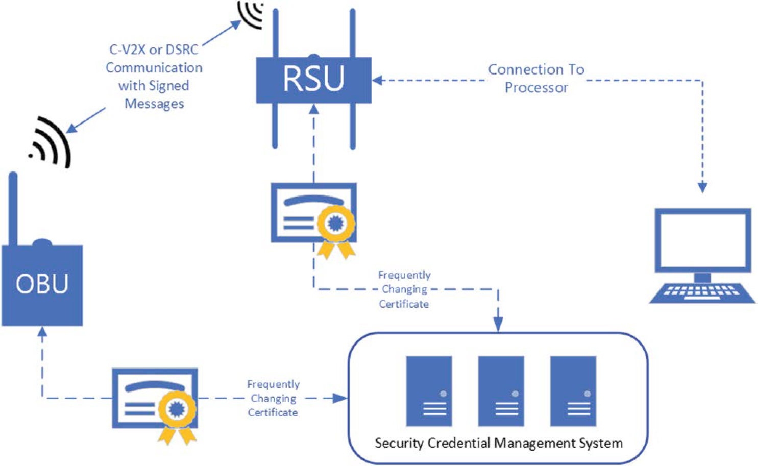
Security Credential Management System
The Security Credential Management System (SCMS) is a message security system proposed to provide end-to-end security for vehicle-to-vehicle or vehicle-to-infrastructure messages within a CV system (U.S. DOT. n.d.-g). The SCMS utilizes a public key infrastructure (PKI) methodology to manage frequently changing digital certificates and public key encryption. This methodology ensures that only enrolled devices can provide information within the system while maintaining privacy. It also enables the ability to identify bad actors within a system and revoke message-sending capabilities to protect the security and integrity of the CV system. The SCMS is typically established at a very high level (either state or federal) to support cooperative involvement with CV deployments within a large region. Doing so allows large-scale compatibility from area to area where a CV system is deployed. The SCMS is an essential part of a CV system, as it enables users and operators to receive information and messages in a secure and trustworthy way while maintaining privacy.
Data Considered
While there are several types of data denoted as CV datasets, the data considered within this chapter, and for the purposes of the use cases described, are data generated by physical CV infrastructure consisting of hardware along the roadway and within vehicles, and not data collected from vehicular probe datasets. Probe data may be considered as third-party datasets that are generally captured from mobile devices or from vehicle manufacturers connections to personal and fleet vehicles, as data are sent over cellular networks and resold as CV data. This chapter does not consider use cases with data derived from probe vehicle or third-party datasets; it focuses on the development of use cases with infrastructure owned and operated by a maintaining agency.
Connected Vehicle Data Size
Most CV systems are very capable of producing big data. Working datasets for CV platforms are very capable of approaching terabytes in size, with archived data growing continuously. While this chapter does not provide guidance on storing, processing, or parsing data, given the varying architecture of transportation management data systems across the nation, readers are strongly advised to roughly calculate their storage and processing needs during the planning of a CV system to maximize the benefits from it. A typical basic safety message (BSM) will range in size from 50 to 481 bytes, depending on information contained within the message and security certificate headings (Cominetti et al. 2022). These messages are broadcast from CV equipment at a frequency of 10 hertz, or 10 times per second. This means that if an RSU were to receive messages from a CV at the full rate for a duration of 20 seconds (the approximate time the CV is within range of the RSU), then the RSU would process up to 96.2Kb of data for that event.
Connected Vehicle Standards
There are several standards guiding the development of CV equipment and the implementation and use of CV systems. This section introduces the governing standards for both DSRC and C-V2X protocols; the SAE standards for CV data and onboard equipment; and the Architecture Reference for Cooperative and Intelligent Transportation (ARC-IT).
DSRC
DSRC is standardized under IEEE 802.11P (IEEE 2010) and several sets of standards under IEEE 1609.X-2016 (IEEE 2009). DSRC is referenced as wireless access in vehicular environments
(WAVE). Approved in 2010, with some of the first implementations completed shortly thereafter, it is the first standard developed for CV communications (IEEE 2011). WAVE technology works similarly to other 802.11 Wi-Fi protocols, using a wireless local-area network (WLAN) to establish communication channels so CVs can communicate with other CV systems within a short range—typically between 200 and 300 meters (VanSickle et al. 2019). The technology operates as a point-to-point or direct communication that allows it to operate at a low latency, providing an effective means of communications for critical operation applications proposed within CVs. DSRC has the capability to communicate directly with vehicles or connected users of the roadway, but it requires that vehicles and users be outfitted with DSRC-specific communication devices.
C-V2X
C-V2X is standardized under the 3rd Generation Partnership Project (3GPP) Releases 14, 15, and 16 (3GPP n.d.-a). C-V2X differs from DSRC in its use of radio technology. DSRC uses WLAN Wi-Fi technology, whereas C-V2X uses cellular radios. As such, C-V2X has the capability to communicate directly with other vehicles and infrastructure as well as indirectly with other entities (e.g., pedestrians, cyclists, and work zone equipment or safety devices) by interfacing with personal information devices or cellular networks. This is possible through C-V2X because the protocol uses two transmission modes: direct communications (PC5) and network communications (Uu). PC5 works independently of cellular networks to communicate with vehicles and other road users, while Uu utilizes traditional cellular networks to enable vehicles to receive real-time information (5GAA n.d.). Since C-V2X falls under the 3GPP, it follows the developments of cellular communication and adapts 5G New Radio (NR) technology to the 5 GHz spectrum (3GPP n.d.-b). DSRC and C-V2X are not compatible and cannot communicate with each other.
SAE
SAE has developed two sets of standards for CVs: a vehicle-to-everything (V2X) Communications Message Set Dictionary under SAE J2735 and On-Board System Requirements for V2V [vehicle-to-vehicle] Safety Communications under SAE J2945/1.
SAE J2735. The SAE J2735 standard develops specific message dictionaries to be referenced by CV equipment manufacturers (SAE 2020-b). This includes data frames and data elements used by applications in V2X systems. The J2735 standard is designed to support interoperability between V2X applications and remain independent of the communication protocol (DSRC or C-V2X) used for data exchange between entities in the CV system. A common reference that is defined inside the J2735 standard is the BSM, which includes “a packet of data that contains information about vehicle position, heading, speed, and other information relating to a vehicle’s state and predicted path” (Lukasik et al. 2020) The BSM is broadcasted from a CV at a rate of 10 times per second. In summary, the SAE J2735 standard provides for a common schema for CV messages by specifying a message set in its data frames and data elements for use by CV applications independent of the underlying communication protocols.
SAE J2945/1. SAE J2945/1 specifies the onboard V2V equipment standards for light vehicles (SAE 2020-a). SAE J2945/1 specifies the profiles, functional requirements, and performance requirements of the onboard equipment. This standard was developed to help BSMs be properly exchanged in V2V applications, maintain interoperability, and maintain data integrity across safety applications.
ARC-IT
The U.S. DOT published the Architecture Reference for Cooperative and Intelligent Transportation as a common language for ITS implementations (U.S. DOT n.d.-a). While ARC-IT does
not mandate specific ITS implementations, its common language encourages interoperability of systems and provides generalized system and data flow architecture. The service packages inside ARC-IT provide generalized system diagrams, data flows, and entities for CV applications. To maintain neutrality, this chapter references the ARC-IT service packages for each of the CV applications discussed in reference to transportation system management with CV data.
Transportation System Management with CV Data
CV data can be a significant source of real-time, high-resolution data that can enhance transportation system management. CV data are expected to be of high quality, accuracy, and integrity independent of region or location. This is due, in general, to standardization of the equipment being used to collect the data and commonalities in CV application data management. While CV data can be a reliable source of real-time transportation system operational data, a high penetration rate of CV-equipped vehicles and RSUs is required to provide enough information to be used for reliable transportation system management. Until penetration rates within a geographic region are high, CV data can be used as an additional set of transportation system management data, where available, and correlated with existing datasets to inform decision making.
The application of data fusion methods, which integrate various data sources to increase data accuracy and utility, can be implemented to combine high-quality CV data with other datasets, such as data received from traditional ITS equipment, roadway network data [e.g., linear referencing system (LRS) data], or other near real-time data and information (e.g., probe data, crowdsourcing data). Data fusion can improve real-time decision-making systems or practices and produce higher confidence intervals for predictive traffic management systems.
Data Fusion Methods
Data fusion methods are focused on the ability to collect, enhance, and distribute multiple data sources and datasets across the network. As a primary function, data fusion combines the various data received from CV OBUs, deployed infrastructure and RSUs, third-party probe and crowdsourced data providers, or other available data. Through data fusion, these disparate data are brought together to allow for a more comprehensive view of the network. This includes supporting analytics to inform traffic operations management and derive performance metrics to support real-time analyses, real-time decision-making, and, in some instances, predictive analyses, given appropriate systems and data (Wei et al. 2022).
To take advantage of advancements in technology, data fusion frameworks often reside in cloud environments designed to quickly scale resources to fit the needs of various use cases. The ability of these environments to fuse data from various systems can be coupled with the wider range of communications options to better complete messaging across the transportation network. This might include activities such as alerting transportation users to events that may affect travel well before the user is at the location of concern. To support these functions, the data fusion environment stores, analyzes, and presents information in near real-time from a centralized platform. Leveraging the tools of the cloud can significantly reduce latency in providing information back to the system and its users. Relying on advanced statistical tools and spatial analysis can further enrich internal and external messaging (e.g., alerts, warnings, and traveler information messages) designed to increase the safety and reliability of the transportation network.
Strategies
Two strategies for transportation management with CV data are discussed later in this chapter: vehicular system management and pedestrian system management. These strategies differ in the
type of data collected and required and in the use cases; however, both can benefit from similar data fusion methods and the underlying environment that supports the data fusion system. Implementing both strategies together provides the opportunity to increase safety and optimize transportation systems.
FHWA Lessons Learned
FHWA has undertaken several CV pilot projects with stakeholders of varying sizes, capabilities, and ITS experience. The pilot programs demonstrated the use of the technology in real-world and practical applications and evaluated the effectiveness of CV systems toward safety, mobility, and operations. Systems of different architectures and technologies were evaluated with different goals and objectives. Lessons from Phase 1 of the pilot programs revealed that most pilot sites reported the need to integrate the use of non-CV technology as part of the deployment and solution to complement the CV system (Deurbrouck and Thompson 2017). Other lessons learned focused on interoperability, functionality, maturity, and best practices for deployment.
Vehicular-Based CV Applications for Transportation Management
Vehicular use cases for CV provide the potential to utilize CV data streams from CV applications for transportation system management. These applications utilize varying types of information flows. These information flows are depicted with data flow diagrams from the ARC-IT service packages to illustrate the general topology and service of each application. Some applications only provide data that can be used with a data fusion methodology for transportation system management. Other applications provide information to transportation system managers and vehicle operators. This section discusses both types of applications and provides a general overview of the vehicular CV system and data.
While many service packages are available through ARC-IT, the service packages discussed in this chapter relate to applications that are currently utilized or have been implemented. Readers should consider the discussion of these applications only as a primer to support a generalized understanding of data flows and potential uses of the CV data collected from each application. Readers seeking a more detailed understanding of existing CV deployments are referred to the U.S. DOT inventory of Operational Connected Vehicle Deployments (U.S. DOT n.d.-c).
Systems/Data
CV systems provide detailed, high-resolution data from the various CV applications. These data are delivered in real time and in high frequency. This section provides insights on three scenarios related to data transmission from CV systems:
- The use of these data to manage arterial and highway systems,
- How the data are provided back to the traveling public (e.g., warning motorists of pending congestion, weather, incidents), and
- How the data support automated safety programs (e.g., queue warning and wrong-way driving alerts).
The development of vehicular use cases considers each of the three environments illustrated in Figure 16-2. In the first scenario, only some vehicles have the capacity to connect to each other via V2V connection or through third-party probe options. The second scenario represents a field-deployed RSU that covers a known area and pushes alerts to the traveling public for those vehicles capable of receiving the alerts. The third scenario is ideal, in that RSUs collect and push
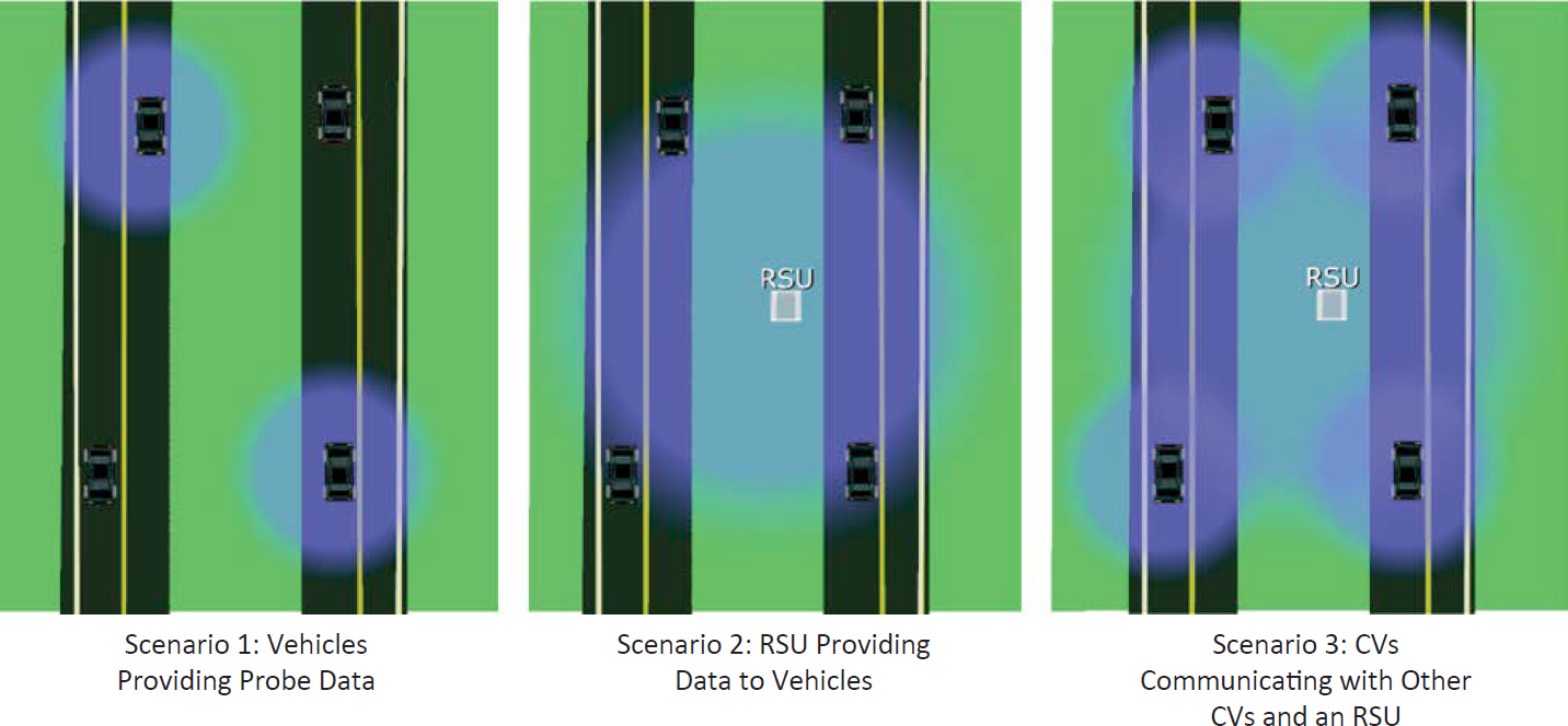
notifications that are shared across CVs. Scenario 3 allows expanded coverage of the CV network and provides multiple options to collect and share information with travelers.
Most CV applications are designed such that they can operate under Scenario 3 where vehicles are able to share information with other vehicles as well as communicate with CV-equipped infrastructure via an RSU. However, some applications are only designed to inform CVs of information related to the infrastructure or receive information from CVs (Scenario 2). These applications are often related to performing basic functions of CV systems such as BSMs, signal phase and timing (SPaT), and MAP applications that provide and collect information related to a single point or to specific intersections. (A MAP is a digital packet of data that describes the geometry of a road or intersection.) The following subsections discuss CV applications in detail and provide information flow diagrams from the ARC-IT documentation for each. The BSM is addressed first since it plays a role in multiple applications.
Basic Safety Message
The BSM is just as the name implies: the basic information provided from CV OBUs containing vehicular operation data per SAE J2735 standards. Data from BSMs are used within various V2X safety applications and are discussed in more depth in the remainder of this chapter. It is important to note that the BSM has two parts. Part 1 is the core message and contains data elements such as vehicle size, position, speed, heading, acceleration, and braking system status. Part 2 of a BSM contains optional data transmitted when required or in response to an event. Part 2 serves as an extension of vehicle safety information and data that pertain to vehicle components such as lights, wipers, and brakes (UMTRI 2022). The BSM is not stored on the OBU and is transmitted in real time, regardless of whether it is in range of an RSU.
Speed Harmonization
Speed Harmonization (ARC-IT Service Package TM21) is a method of dynamically controlling speed limits on highways that experience significant peak volumes, incidents, or adverse weather conditions to increase safety and reduce congestion (U.S. DOT n.d.-h). This application
is a user feedback application. It uses real-time BSM data and traffic operational data to provide OBUs or suggested speeds on dynamic speed signs to alleviate existing or future (i.e., predicted) congestion. The data within Part 1 of a BSM are readily available within an operational CV system. Vehicle location, heading, and speed data support the implementation of dynamic speed harmonization. The location data are used to position the data point within the transportation system, the heading data from the OBU’s internal Global Positioning System (GPS) determine and confirm the directionality of the vehicle that observed the measurement, and the speed is captured from the vehicle’s data or GPS system. Together, the location, heading, and speed data inform the suggested speed based on calculations made by the dynamic speed harmonization application running at the traffic management center.
Where penetration rates of equipped vehicles are low, dynamic speed harmonization systems may require additional data from third parties such as vehicle probe data. Furthermore, in areas where there are gaps in roadside CV equipment, the same third-party data can be applied and fused with the observed CV measurements to achieve a high confidence of dynamic speed harmonization. The recommended speed on dynamic speed signs can be adjusted along the corridor, and data can be provided to CVs via the OBU to provide the vehicle’s systems or the driver the recommended speed to travel along the corridor.
The diagram in Figure 16-3 depicts a general data flow and system interactions for the dynamic Speed Harmonization application.
Queue Warning
Queue Warning applications (ARC-IT Service Package VS08) provide warning messages to vehicles that are approaching a stopped or slowly moving queue (U.S. DOT n.d.-e). The warning is intended to alert approaching motorists of a potential unexpected stop or slowdown ahead that may or may not be visible. Queue warning applications are typically implemented with traditional ITS applications (video detection) at interchanges, major intersections, or along facilities where reoccurring queueing occurs and where the line of sight may be restricted by geometry such as horizontal or vertical curves.
CV queue warning applications can be implemented along roadway networks with potentially less infrastructure or cost than traditional applications, as they would only rely on the penetration rate of the CV equipment (RSU and OBU). CV-based queue warning applications are mostly autonomous applications that rely on traffic operational data via ITS devices or BSMs. The data are leveraged to provide advanced notice to vehicles approaching the back of the queue in congestion or at intersections where visibility or line of sight may be limited. These applications will automatically trigger notifications via dynamic message signs (DMS), roadside blank-out signs, CV messages, or other means of motorist notification when a queue has been detected beyond a predetermined threshold distance. When CVs are the data source, data from Part 1 and Part 2 of the BSM can potentially be used to determine when a queue is present and the back of the queue as well as to provide advanced warning to approaching vehicles.
Currently, CVs broadcast their status information to RSUs within range and, when in a queue, to vehicles still upstream of the queue capable of receiving a CV message. As for data broadcast and received by an RSU, the transportation management center that receives the data can process the queued status and relevant BSM information within a queue warning application to determine whether the vehicle is disabled or indeed within a queue. BSM data with braking statuses can be observed within the queue warning application to identify the back of the queue and decide whether the advanced warning needs to be broadcasted further upstream to CVs or a DMS. Additionally, location data from the CV coupled with MAP message data can help identify the traffic patterns and details of the queue for each affected lane.
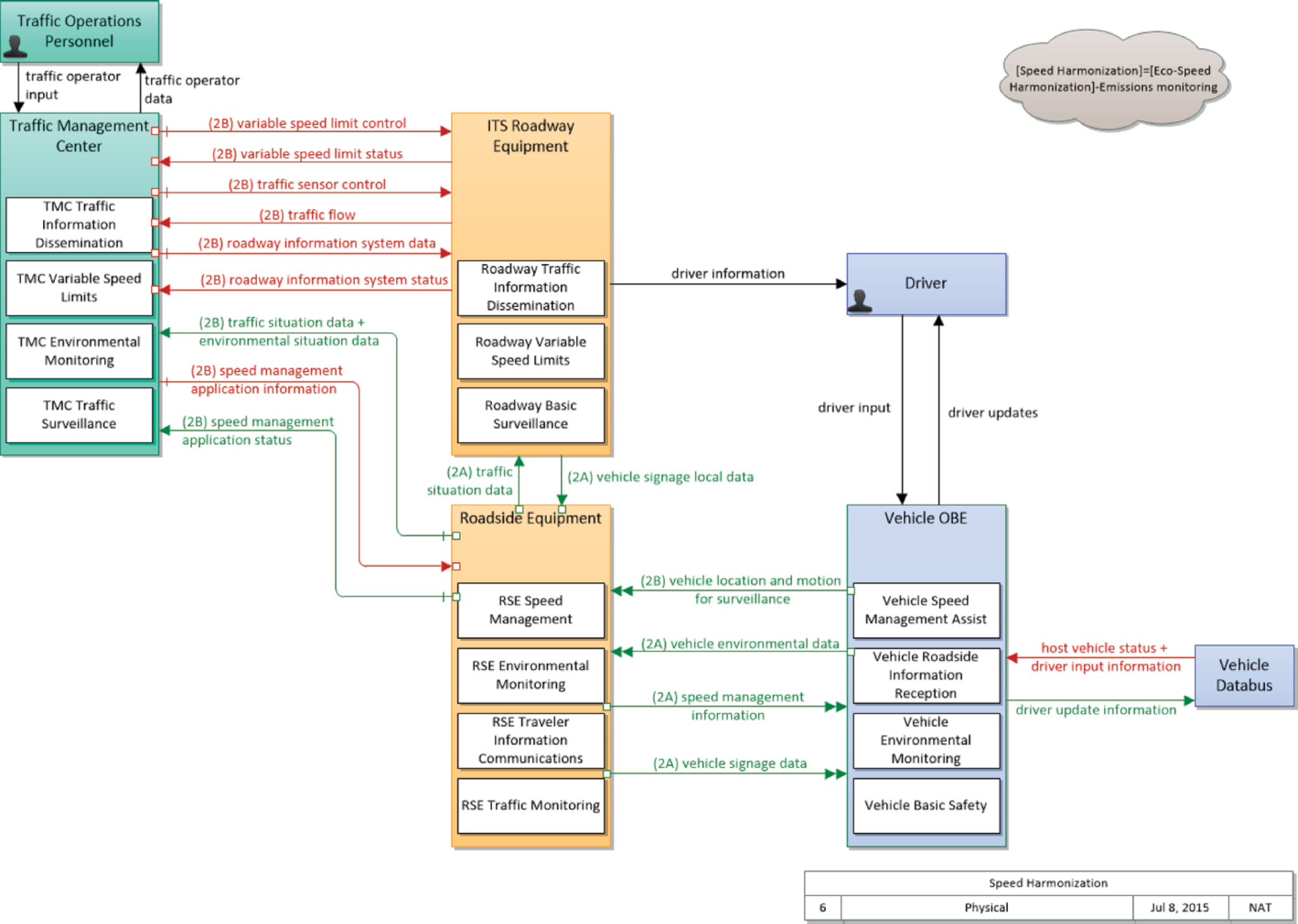
Source: U.S. DOT (n.d.-h).
Note: TMC = traffic management center; RSE = roadside equipment; OBE = onboard equipment.
Where penetration rates of CV are low, the queue warning system can utilize fused data from third-party probe data, ITS sensors, and CV system data. Probe data showing real-time speeds provide generalized hot spot information. ITS sensor data can then be applied to understand the exact limits of queues. ITS sensor data can come in the form of radar detection for speed, computer vision systems to identify stopped vehicles, or other traffic observation systems and sensors. The use of fused data within the queue warning application enhances the ability to detect and determine queue parameters in real time. The diagram in Figure 16-4 depicts a general data flow and system interactions for the Queue Warning application.
Wrong Way Vehicle Detection and Warning
Wrong Way Vehicle Detection and Warning systems (ARC-IT Service Package TM25) assist in detecting a motor vehicle that has entered an arterial or highway facility in the wrong direction and alerting the transportation management center and other road users (U.S. DOT n.d.-k). These systems traditionally operate by using traffic detection systems or other ITS-based solutions. CV wrong way detection can provide (1) wrong way detection with both MAP messages and BSMs and (2) real-time in-vehicle feedback to alert motorists if a wrong way event occurs and if a collision is possible. While ITS-based solutions for detection of wrong way driving exist, they are typically cost prohibitive to place at every interchange and along corridors in high-density areas because of the nature of the complex roadside equipment required. The use of CVs for wrong way detection applications provides an opportunity for continuous monitoring wherever CV equipment is installed. This application is effective when penetration rates of CVs achieve a majority share of vehicles on the roadway and can work in tandem with ITS equipment to detect and notify. On the basis of the MAP message and BSM of the vehicle, when a vehicle equipped with CV technology enters an exit ramp or the opposing travel lanes traveling in the wrong direction, a wrong way detection system can detect that the vehicle is in violation and immediately provide a notification to that specific vehicle. Should the vehicle continue in the wrong direction, the system can alert the transportation management center to provide both notification via DMS and a CV warning message to CV-equipped vehicles upstream. The diagram in Figure 16-5 depicts a general data flow and system interactions for the Wrong Way Vehicle Detection and Warning application.
Weather-Responsive Traffic Management
Weather can significantly impact the performance of the transportation system. CV systems can report specific situations within microregions of a transportation system. The Road Weather Motorist Alert and Warning application (ARC-IT Service Package VS07) can support weather-responsive actions from a regional or local transportation management center (U.S. DOT n.d.-f). The data provided from a BSM can support the diagnostics to determine whether significant weather events trigger advanced notification for the traveling public approaching an area of concern. The data can also support notifying operators to dispatch personnel and equipment to implement treatments, diversions, or closures. Weather-responsive traffic management requires BSM data related to vehicle functions, such as wiper status, vehicle-observed temperature, rain sensor status, sun sensor status, exterior lighting status, traction control status, and braking status. These data sent through the BSM are analyzed by centralized applications at the transportation management center to determine the need to issue road weather advisory information or initiate diversion plans during severe weather situations.
Where the penetration of CVs in a transportation network is lower, it may be necessary to fuse data from external weather service systems and ITS roadway equipment with CV data to determine the severity of the weather event and the level of response required. CVs offer the
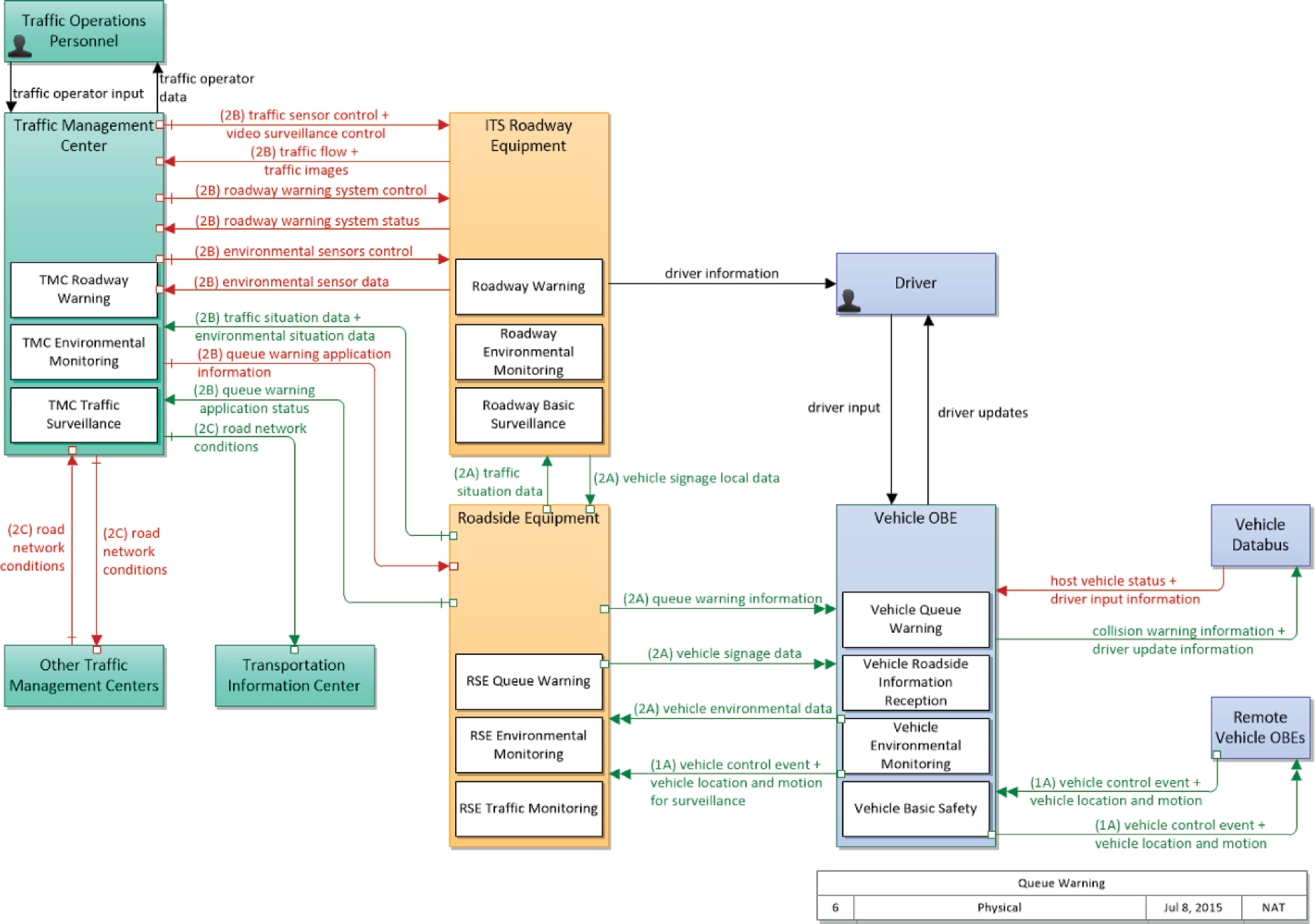
Source: U.S. DOT (n.d.-e).
Note: RSE = roadside equipment; OBE = onboard equipment.
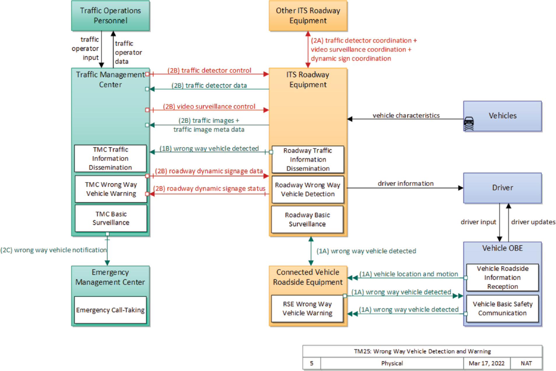
Source: U.S. DOT (n.d.-k).
Note: TMC = traffic management center; RSE = roadside equipment; OBE = onboard equipment
transportation system a significant opportunity to understand the impact of localized weather events. Additionally, fusing CV data with other data sources may allow for predictive responses to alert motorists to upcoming conditions.
The diagram in Figure 16-6 depicts a general data flow and system interactions for the Road Weather Motorist Alert and Warning application.
Freight Signal Priority
Freight vehicles—specifically loaded freight vehicles—have a more significant impact on the transportation system than normal passenger vehicles. These vehicles require more distance to stop than passenger vehicles. Frequent starts and stops by freight vehicles at signalized intersections not only cause significant wear to the vehicles but also affect the infrastructure, producing rutting along freight corridors.
Freight signal priority, which grants a low-level priority request to the advanced traffic controller at an intersection, is intended to
- Increase safety by decreasing arrivals on yellow or red within the decision zone of the approach,
- Increase the efficiency of major freight networks by reducing delay of loaded freight vehicles, and
- Decrease localized environment impacts and roadway wear by decreasing stopping and starting by heavy freight vehicles at signalized intersections.
The ability to detect loaded freight vehicles further upstream than traditional ITS solutions allow (e.g., video detection, induction systems), gives signal systems at an intersection more time to grant priority to an approaching loaded freight vehicle by extending the green phase that otherwise would have been yellow or red when the freight vehicle reached the intersection.
The Freight Signal Priority application (ARC-IT Service Package CVO06) is dependent on various systems and communications between the transportation management center, the freight vehicle, and freight management centers (U.S. DOT n.d.-b). Thus, this application is more complex than most CV applications. However, it provides extended safety and operational benefits by potentially reducing the chances of a truck running a red light or multiple trucks contributing to increased congestion along signalized corridors.
While ITS solutions at freight terminal entrances can provide signal priority for queued trucks or those approaching signals, arterial freight signal priority calls require additional measures or means to determine whether a call is necessary. Ideally, only loaded vehicles should receive priority; thus, a method to determine whether the vehicle is loaded is required. These methods will often be expensive or require interaction from the driver of the freight vehicle and may still result in a high percentage of unnecessary priority requests. If the vehicle is not equipped with CV equipment, ITS sensors, such as weigh-in-motion systems or advanced camera and weight-detection systems, may be required to determine whether a truck is loaded. However, with the CV application, the requests are tied to interaction from a fleet or freight management center to confirm that the vehicle is, in fact, loaded. This added layer of communication requires an additional component (the intermodal terminal or the fleet and freight management center) as part of the CV information flow. The diagram in Figure 16-7 depicts a general data flow and system interactions for the Freight Signal Priority application. As shown in Figure 16-7, the added layer of communication requires validation checks and human interfaces within the freight vehicles to confirm the priority request via the CV driver input. Only when the request has been validated will the application at the transportation management center push the priority call to the intersection signal controller. However, priority should not be guaranteed in the instance that an emergency vehicle priority request or rail preemption request has been made.
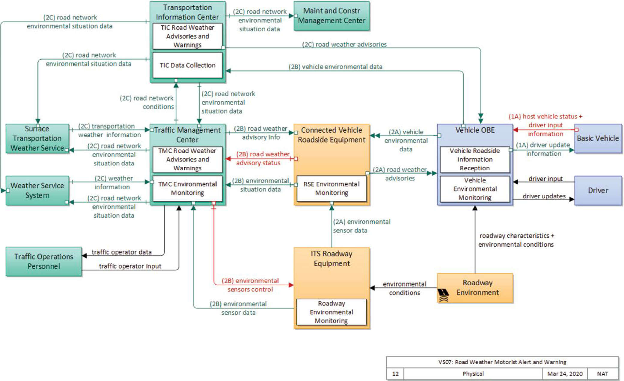
Source: U.S. DOT (n.d.-f).
Note: TIC = transportation information center; TMC = traffic management center; RSE = roadside equipment; OBE = onboard equipment.
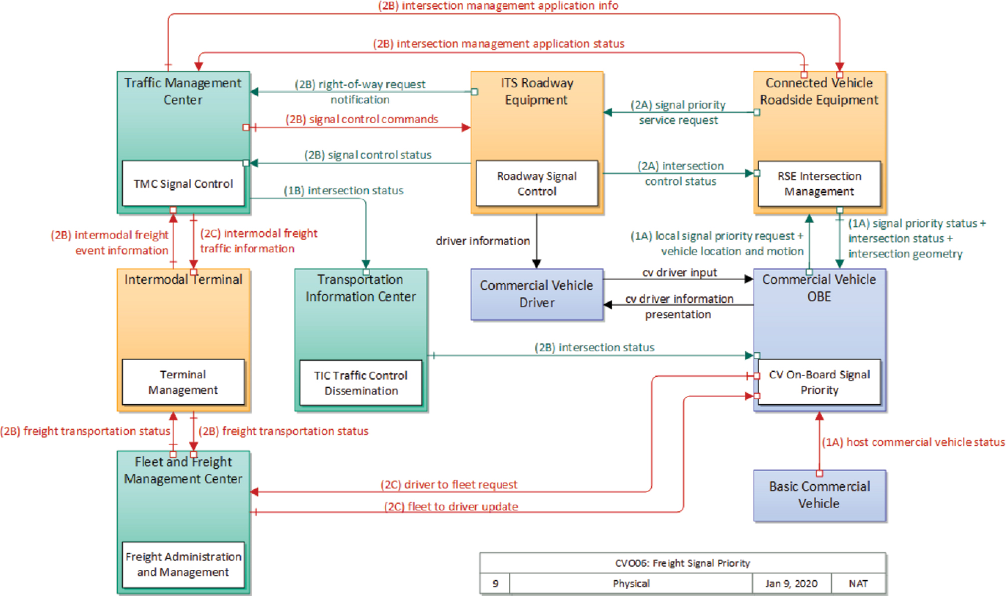
Source: U.S. DOT (n.d.-b).
Note: TMC = traffic management center; RSE = roadside equipment; TIC = transportation information center; OBE = onboard equipment.
Pedestrian and Cyclist CV Applications for Transportation Management
Pedestrian and cyclist connectivity to the infrastructure system is provided by emulated OBUs with smartphone applications; pedestrian-specific OBUs, such as a connected smart vest worn for roadside worker detection systems; or specially designed OBUs worn by pedestrians or cyclists. The data from these systems are used to implement pedestrian and cyclist detection and motorist alerts in areas with nonmotorized users. This discussion focuses on the data supporting these systems; how the data are being used to support safety and mobility applications; and opportunities for improvements to pedestrian and cyclist system management.
Vulnerable Road User Safety Application
Pedestrian and cyclist detection with a CV system provides increased opportunities for creating a safe environment for the most vulnerable road users. The Vulnerable Road User Safety application (ARC-IT Service Package VS-12) focuses on detecting pedestrians and cyclists and providing feedback to motorists, ITS equipment, and the transportation management center (U.S. DOT n.d.-d). Feedback to pedestrians and cyclists may also be provided, depending on the functionality of their OBU or emulated OBU. This feedback includes an indication of their detection at intersections or warnings of conflicting vehicles approaching.
This application extends the detection capabilities of active and passive pedestrian and cyclist detection systems by providing connectivity to personal information devices (PIDs) such as emulated OBUs (smart devices with connected applications) or connected pedestrian devices with RSUs at intersections. The use of connected pedestrian systems extends the range of detection at the intersection and provides high-resolution data for pedestrian location and trajectory at the intersection. This supports advanced notification to motorists and ITS equipment. Priority can be provided to connected pedestrians for specific scenarios and to extend pedestrian phases for pedestrians who remain in a crosswalk after the pedestrian phase has ended. The diagram in Figure 16-8 depicts a general data flow and system interactions for the Vulnerable Road User Safety application.
The data from the Vulnerable Road User Safety application can be observed at the transportation management center. Pedestrian metrics such as volume, crossing time, abandonment, and pedestrian type can be observed and utilized at the operations level to understand whether signal-timing or safety improvements should be made. Additionally, these data metrics provide the ability to track performance of the multimodal system over time.
Transit Pedestrian Indication
Advanced detection for transit users can provide critical transit route optimization and enable on-demand flex route services. Utilizing pedestrian CV systems can greatly decrease the infrastructure costs of expanded transit systems and provide real-time feedback to transit users regarding scheduling and service updates enroute. The Transit Pedestrian Indication application (ARC-IT Service Package PT11) utilizes PIDs capable of communicating with the CV application to provide position/location and status (e.g., waiting for bus) (U.S. DOT n.d.-i). Some PID applications that communicate with transit management systems allow the user to indicate which route and stop they are requesting or intending to utilize; others may only provide information on the transit system. The diagram in Figure 16-9 depicts a general data flow and system interactions for the Transit Pedestrian Indication application.
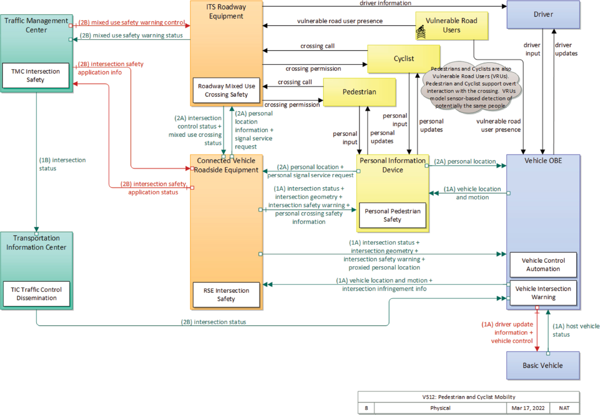
Source: U.S. DOT (n.d.-d).
Note: TMC = traffic management center; TIC = transportation information center; RSE = roadside equipment; OBE = onboard equipment.
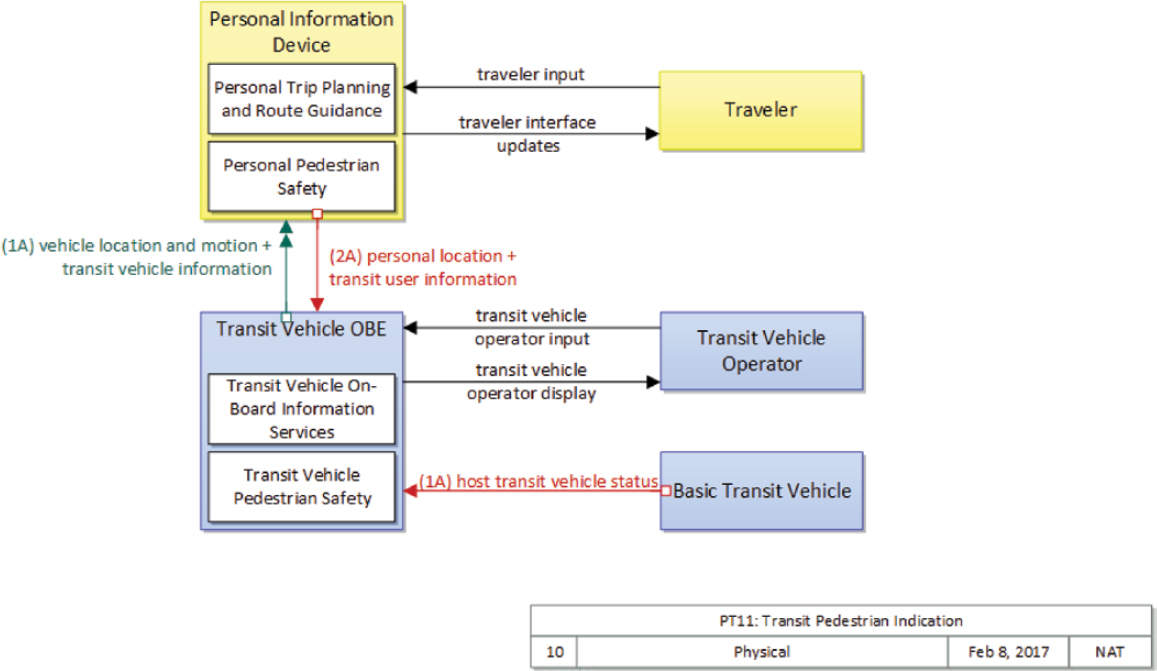
Source: U.S. DOT (n.d.-i).
Note: OBE = onboard equipment.
Summary and Recommendations
The purpose of this chapter is to provide insights, resources, and discussion of the use of CV data for transportation systems management. As of the writing of this chapter, the number of CV implementations was limited, with many intersystem incompatibilities due either to differences in radios (DSRC, C-V2X) or to other reasons within the infrastructure itself. For this reason, there was no single large regional area that could be observed or studied to understand the full impact of CV data for transportation systems management. However, the standards discussed at the beginning of this chapter and the common architecture for CV applications within ARC-IT illustrate how data can be extracted from CV systems and used to assist in transportation system management. Fusing data from CV systems with existing data from infrastructure sensors or third-party data such as probe data can greatly enhance data availability and reliability and, ultimately, provide more information to traffic management centers making real-time and predictive decisions for safety and operations.
As the transportation infrastructure evolves, CV equipment will become more prevalent at the roadside. Auto manufacturers have provided timelines for including OBU installations as standard equipment in new vehicles, and some vehicles are equipped today. It is anticipated that over the next 10 to 15 years, adoption levels for CV technology will increase rapidly, and the data from these systems will be available in greater densities and resolutions in most urban areas. Therefore, the need to coordinate as a region is essential for the development of these projects. Properly developed projects will involve coordination between local and regional agencies. This coordination will enhance interoperability and data sharing across jurisdictional boundaries, increasing the amount of data available for transportation system management at the regional level and improving safety, efficiency, and reliability for all users.
References
Cominetti, E. L., Silva, M. V. M., Simplicio, M. A., Jr., Patil, H. K., and Ricardini, J. E. (2022). Faster Verification of V2X BSM Messages via Message Chaining. Cryptology ePrint Archive. https://eprint.iacr.org/2022/133.pdf.
Deurbrouck, T., and Thompson, K. (2017). U.S. Department of Transportation, Intelligent Transportation Systems Joint Program Office. (2017, 01 30). Connected Vehicle Pilot Deployment Program Phase 1: Lessons Learned. Final Report. Retrieved from https://rosap.ntl.bts.gov/view/dot/31937.
5GAA. (n.d.). Connected Mobility/C-V2X Explained. https://5gaa.org/c-v2x-explained/.
IEEE. (2009). IEEE 1609—Family of Standards for Wireless Access in Vehicular Environments (WAVE). https://www.standards.its.dot.gov/Factsheets/Factsheet/80.
IEEE. (2010). IEEE Standard for Information Technology—Local and Metropolitan Area Networks—Specific Requirements—Part 11: Wireless LAN Medium Access Control (MAC) and Physical Layer (PHY) Specifications Amendment 6: Wireless Access in Vehicular Environments. IEEE Standards Association. IEEE 802.11p-2010. https://standards.ieee.org/ieee/802.11p/3953/.
IEEE. (2011). Standard for Wireless Access in Vehicular Environments (WAVE)—Over-the-Air Electronic Payment Data Exchange Protocol for Intelligent Transportation Systems (ITS). IEEE 1609.11-2010. https://standards.ieee.org/ieee/1609.11/4950/.
Lukasik, D., Hale, D., Ma, J., Shibley, P., Malone, T., Chandler, A., Cleary, C., Matout, N., and Adebisi, A. (2020). Enhancing Active Transportation and Demand Management (ATDM) with Advanced and Emerging Technologies and Data Sources. Washington, DC: U.S. Department of Transportation, FHWA. https://ops.fhwa.dot.gov/publications/fhwahop19010/fhwahop19010.pdf.
SAE. (2020-a). On-Board System Requirements for V2V Safety Communications J2945/1_202004. https://www.sae.org/standards/content/j2945/1_202004/.
SAE. (2020-b). V2X Communications Message Set Dictionary J2735_202007. https://www.sae.org/standards/content/j2735_202007/.
3GPP. (n.d.-a). Specifications and Technologies/Releases. https://www.3gpp.org/specifications-technologies/releases.
3GPP. (n.d.-b). Specifications and Technologies/Releases/Release 17. https://www.3gpp.org/specifications-technologies/releases/release-17.
UMTRI (University of Michigan Transportation Research Institute). (2022). Safety Pilot Model Deployment: Rx Basic Safety Messages. Ann Arbor, MI: Center for the Management of Information for Safe and Sustainable Transportation. https://deepblue.lib.umich.edu/bitstream/handle/2027.42/175813/Safety%20Pilot%20Model%20Deployment%20-%20Rx%20Basic%20Safety%20Messages%20Codebook.pdf?sequence=2&isAllowed=y.
U.S. DOT. (n.d.-a). Architecture Reference for Cooperative and Intelligent Transportation (ARC-IT). https://www.arc-it.net/.
U.S. DOT. (n.d.-b). CVO06: Freight Signal Priority. Retrieved June 29, 2022, from https://www.arc-it.net/html/servicepackages/sp33.html#tab-3.
U.S. DOT. (n.d.-c). Operational Connected Vehicle Deployments in the U.S. https://www.transportation.gov/research-and-technology/operational-connected-vehicle-deployments-us.
U.S. DOT. (n.d.-d). Pedestrian and Cyclist Safety. Retrieved June 29, 2022, from https://www.arc-it.net/html/servicepackages/sp50.html#tab-3.
U.S. DOT. (n.d.-e). VS08: Queue Warning. https://www.arc-it.net/html/servicepackages/sp52.html#tab-3.
U.S. DOT. (n.d.-f). VS07: Road Weather Motorist Alert and Warning. Retrieved June 29, 2022, from https://www.arc-it.net/html/servicepackages/sp46.html#tab-3.
U.S. DOT. (n.d.-g). Security Credential Management System (SCMS). https://www.its.dot.gov/resources/scms.htm.
U.S. DOT. (n.d.-h). TM21: Speed Harmonization. https://www.arc-it.net/html/servicepackages/sp68.html#tab-3.
U.S. DOT. (n.d.-i). PT11: Transit Pedestrian Indication. Retrieved June 29, 2022, from https://www.arc-it.net/html/servicepackages/sp78.html#tab-3.
U.S. DOT. (n.d-k). TM25: Wrong Way Vehicle Detection and Warning. Retrieved June 29, 2022, from https://www.arc-it.net/html/servicepackages/sp213.html#tab-3.
VanSickle, S., Ahmed-Zaid, F., Krishnan, H., Khatchatrian, T., Mahmud, S., Moradi-Pari, E., Probert, N., Ahmad, S., Kamthan, S., Gallagher, B., and McNew, J. (2019). Vehicle-to-Vehicle Communications Research Project (V2V-CR): DSRC and Wi-Fi Baseline Cross-Channel Interference Test and Measurement Report. U.S. Department of Transportation, National Highway Traffic and Safety Administration. Washington, DC. https://www.nhtsa.gov/sites/nhtsa.gov/files/documents/v2v-cr_dsrc_wifi_baseline_cross-channel_interference_test_report_pre_final_dec_2019-121219-v1-tag.pdf.
Wei, H., Kashyap, G., Nian, D., and Lin, W. (2022). V2I-Based Intelligent Mobility Data Fusion for Self-Adaptive Traffic Signal Control. In International Conference on Transportation and Development 2022: Traffic Operations and Engineering (H. Wei, ed.), Reston, VA: American Society of Civil Engineers. https://ascelibrary.org/doi/10.1061/9780784484326.020.


