Enhancing Airport Access with Emerging Mobility (2025)
Chapter: 8 Facility Requirements
CHAPTER 8
Facility Requirements
Purpose
This chapter provides an overview of the facility requirements associated with the integration of each mode or group of modes at aviation facilities. It does not pretend to be a “go-to manual” for the planning and design of non-aviation transportation infrastructure, but rather it is a resource to understand the overall requirements for strategic decision-making, programming, and coordination purposes. Resource documents for planning and design purposes are referenced throughout the chapters. Additional references can be found in the searchable electronic library of the companion toolkit of the report, which is available on the National Academies Press website (nap.nationalacademies.org) by searching for ACRP Research Report 269: Enhancing Airport Access with Emerging Mobility.
Micromobility
Overall Requirements
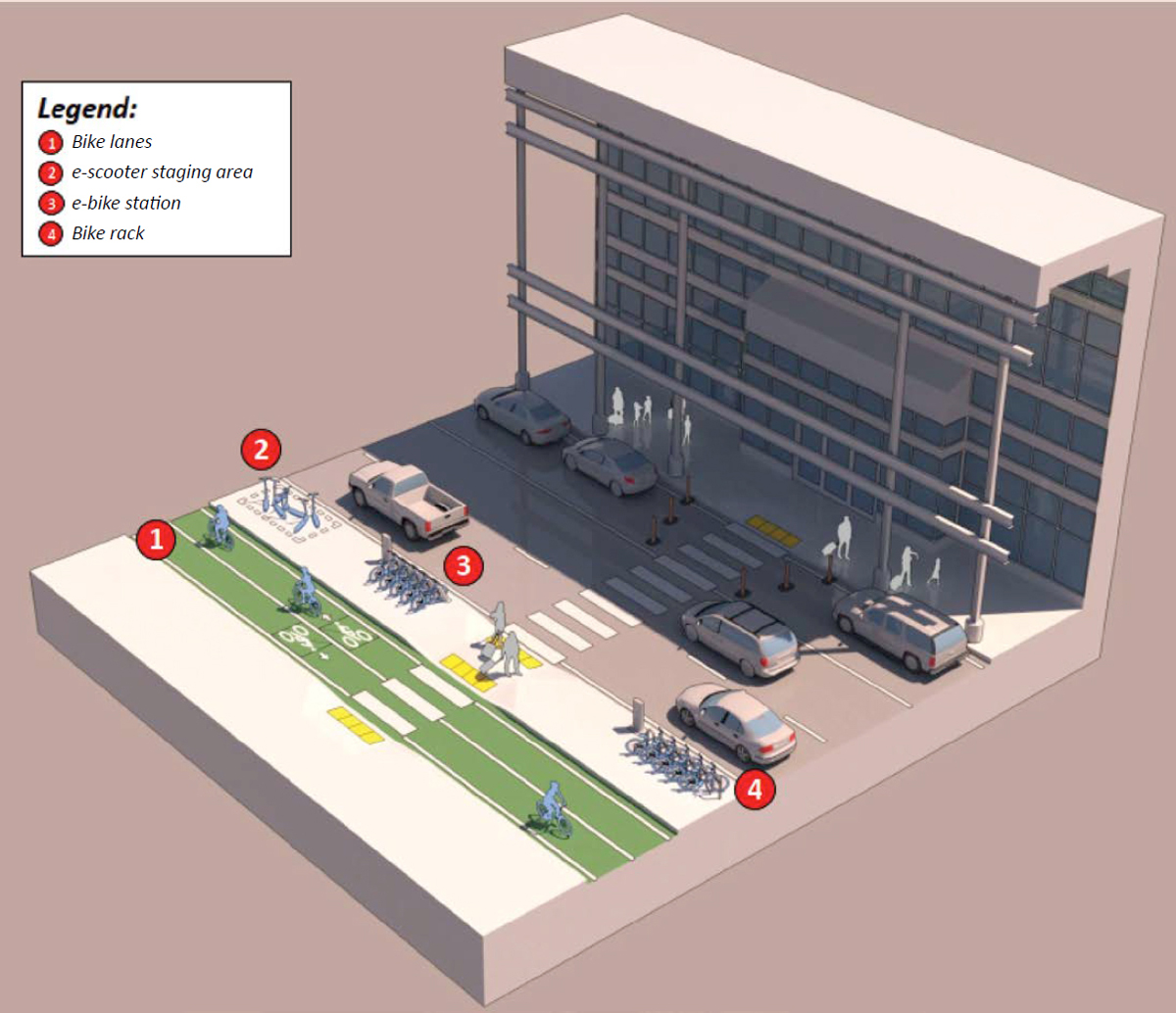
Figure 54 depicts the main infrastructure for micromobility. Micromobility facilities are generally divided into two types: on-street and off-street. Facilities may be shared with other users, such as lanes shared between bicyclists and motorized traffic or pathways shared between bicyclists and pedestrians.
- On-street bicycle facilities are defined as facilities where users travel on roadways with motorized traffic, either by sharing a travel lane with motor vehicles or by having dedicated on-street bike lanes, paved roadway shoulders, or bike lanes separated from motorized vehicles by a painted island buffer. Factors to consider when designing for on-street micromobility facilities include safety, traffic volumes and speeds, presence of on-street parking, frequency of right-turning vehicles, and the degree to which bicyclists are separated from motor vehicle traffic. When bicycle traffic shares the same facilities as motor vehicles, the flow and speed of bicyclists can be significantly impacted because they must maneuver through constrained space and often wait behind queues of vehicles, which limits the ability to travel at free-flow speeds.
- Off-street bicycle facilities are facilities that may be located parallel to roadways or completely independent from the roadway network, such as recreational trails. These facilities may include pathways for the exclusive use of bicyclists or pathways shared with pedestrians. Factors to consider when designing for off-street micromobility facilities include the presence of opportunities for passing maneuvers, frequency of crossing pedestrians, and presence of intersections along the path.
Key Design Features
In planning for micromobility vehicle–space requirements, there are various elements that constitute the operational footprint. The design of safe and efficient micromobility infrastructure is essential to ensure that users are comfortable enough to commute via micromobility services and for micromobility to succeed as a viable transportation mode (National Association of City Transportation Officials 2019a). This requires an encompassing design of various elements, including designated lanes, cycle tracks, intersection treatments, signals and wayfinding signs, pavement markings and parking, and storage and docking space. The National Association of City Transportation Officials (NACTO) has published several guidelines for designing and implementing micromobility, including Urban Bikeway Design Guide and Bike Share Station Guide.
Bike lanes are defined as a section of the roadway designated by pavement marking and signage to indicate preferential or exclusive use for bicyclists or other forms of micromobility vehicles. Bike lane width typically ranges between 4 and 6 feet. The Highway Capacity Manual: A Guide for Multimodal Mobility Analysis, 7th Edition (HCM7) (2022) recommends a standard width for an effective bicycle lane of 3.5 to 4 feet. In the case of off-street bicycle pathways, AASHTO recommends a width of 10 feet; this allows users to travel at the maximum allowable speed without mixing with motorized traffic. Typically, bike lanes run near the curb and adjacent to parked cars in the same direction of traffic, but they may be designed for the contraflow direction in the case of low-volume traffic segments.
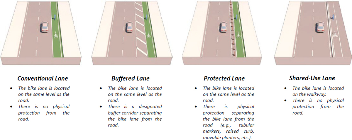
In the case where a physical barrier, such as a median or raised curb, is provided to eliminate encroachment of motorized traffic and provide more safety, these are referred to as cycle tracks. Robert Schneider from the University of Wisconsin–Milwaukee recommends having designated lanes for micromobility vehicles starting within a mile from the designated parking facility at the airport, with well-communicated wayfinding signs to help guide users in advance of the traveled path. These signs increase their comfort level with using this mode of transportation and promote compliance with regulated operations at the airport. Figure 55 depicts the four main bike lane configurations.
Capacity
According to HCM7, the capacity of a bicycle facility depends on the number of effective lanes used by bicycles. Shared-lane facilities typically consist of one effective lane, while designated bicycle lanes, shoulder bikeways, and cycle tracks may include more than one effective lane (based on lane width), and therefore, they can provide greater capacity. Furthermore, a greater number of effective lanes at bicycle facilities provides a higher level of service (LOS) since it offers more opportunities for passing and maneuvering around other users (bicyclists and pedestrians).
In designing for bicycle lanes, HCM7 also recommends a saturation flow rate of 2,000 bicycles per hour per lane for a one-direction bicycle lane under interrupted-flow conditions, equivalent to 1,000 bicycles per hour per lane when the bicycle lane receives a green signal during 50 percent of the signal cycle at signalized intersections.
Parking Footprint
Parking facilities and vehicle storage to accommodate parked or docked vehicles are among the main challenges faced when planning for shared micromobility, and they are an important aspect of the footprint of these vehicles. There are two main types of shared micromobility: station-based and dockless systems. The former dictates the assigned station locations where users can start or end their trip, while the latter allows users to start or end their trip almost anywhere. In practice, some cities allow shared micromobility operators, using public rights-of-way, to leave the vehicles in in-street corrals or designated parking zones in highly congested areas or in designated zones of sidewalks. Designating the drop-off location provides more control over the start and end of these vehicles’ usage and reduces encroachment on the public right-of-way. However, if vehicles are parked on the sidewalk, it is important to ensure that they do not impede the movement of people walking on the sidewalk and that they are compliant with ADA requirements.
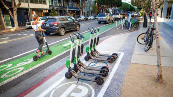
In Santa Monica, California, where one of the largest e-scooter operators started, staging areas for shared e-scooters were created by utilizing a curb bulb-out space at a mid-block crosswalk, as seen in Figure 56 (Transportation for America 2020).
A key difference between parking requirements for private and shared use is that for private micromobility vehicles, storage space needs to be provided for passengers using their own bikes or e-scooters to get to the airport and storing their micromobility vehicles for the duration of their trip. In contrast, shared micromobility vehicles may require docking space for users to drop off or pick up their vehicle, or users may need designated zones at the airport to park their micromobility vehicles for other users to pick up. Furthermore, regular bicycles require more space than foldable and compact bicycles or e-scooters. Nonetheless, shared micromobility has greater flexibility with space needs since micromobility vehicles occupy less space than motorized vehicles.
Integration at Airports
Micromobility (e.g., bikes and e-scooters) can be integrated into airport ground access, especially at downtown airports and with the emergence of additional urban airports that can be incorporated into advanced air mobility (AAM) networks. Driven by the need to reduce curb congestion and vehicle-related emissions, especially at congested airports, operators may be considering methods to increase multimodal transportation at their airports. However, when designing for micromobility access at airports, many factors come into play. The layout and location of the airport can be a physical barrier if it is located in a remote area, and the absence
of multimodal connectivity to transit can also become a challenge for commuting over large segments. In many cases, the traveling public may be weighed down with luggage that prevents them from using micromobility vehicles.
A study by Orrick and Frick (2012) presented several case studies of airport operators that have incorporated employee bicycle access into their airport ground access in an effort to reduce single-occupancy vehicle travel at the airport. The following is a summary of various micromobility facilities among the airports studied:
- Portland International Airport (PDX): trail access through a multiuse path, bicycle racks, secure parking for passengers and employees, in-terminal assembly station for passengers’ boxed bikes, and conventional bicycle parking.
- San Francisco Bay Oakland International Airport (OAK): trail access, bicycle parking, and a bicycle lane constructed on the airport access road by eliminating a traffic lane in each direction.
- Los Angeles International Airport (LAX): bicycle lane on a service road, providing a connection to recreational bicycle paths; bicycle lockers heavily used by airport employees; and showers and a changing area.
- San Francisco International Airport (SFO): trail access, a bicycle lane on a service road that was constructed by replacing vehicle lanes with bike lanes, and bicycle parking.
Several factors contribute to the cycling quality of service, including the volume and speed of adjacent vehicles sharing the same facilities, presence of on-street parking, pavement quality and the frequency of street sweeping, inclement weather, and snow clearing in the case of heavy snow events. These factors, among others, contribute to the safety of using micromobility facilities and can impact the variation of trip demand. Users of micromobility vehicles are more exposed to weather elements—Nosal and Miranda-Moreno (2014) found that precipitation events have a significant negative impact on cycling flows.
In planning for micromobility integration at airports, it is important to consider all the applicable planning and land use requirements based on the owner and operator of the airport, such as state, city, or county planning requirements. In addition, when planning for future facilities, planners can use forms of public outreach, such as surveys or open houses, to better understand the needs of users and commuters. If existing facilities already exist, planners should consider using public surveys to evaluate user satisfaction with existing facilities and assess any enforcement or safety issues encountered to improve these facilities.
In addition, FHWA published a guide for local and state agencies to promote and support the development of safe and complete pedestrian and bicycle networks. The document features guidance and best practices on policies and practical implementation (Louch et al. 2016). In addition, BTSCRP Research Results Digest 1: E-Scooter Safety: Issues and Solutions provides important lessons learned on e-scooter safety management practices (Sandt et al. 2022).
Personal Rapid Transit
Overview
Personal rapid transit (PRT) is a type of guided transportation system made of guideways and “pods” that provides on-demand, point-to-point connections (Figure 57). While similarities exist between PRT and automated people movers (APMs)—defined as “a guided transit mode with fully automated operation, featuring vehicles that operate on guideways with exclusive right of way” (American Society of Civil Engineers 2002)—APMs are more widely used for passenger conveyance and transfers, such as circulation between terminals and access to parking garages,
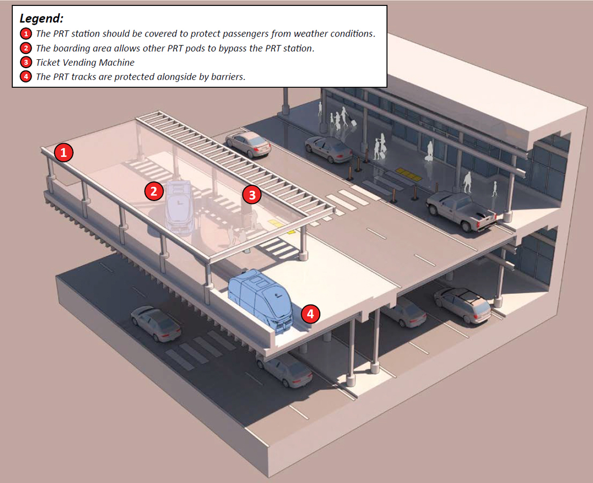
ground transportation centers (GTCs), and consolidated rental car (CONRAC) facilities. This project focuses on airport ground access and draws on similarities between the two modes to discuss existing standards and facility requirements.
A set of standards does not currently exist for PRT system specifications; however, since PRT is considered a type of Automated Transit Network, standards for PRT systems are deferred to ASCE’s APM standards. These standards establish the minimum set of requirements necessary to achieve an acceptable level of safety and performance for APM systems.
ASCE Standard 21 includes minimum requirements for the design, construction, operation, and maintenance of APM systems.
The main infrastructure components of PRT systems include
- Guideways: can be elevated, at-grade, or below-grade and can be built for two-way operations in case of high demand.
- Vehicles: driverless electrically powered vehicles with onboard batteries or wayside third rails that can carry up to 8 passengers per vehicle, or up to 24 passengers per vehicle in the case of group rapid transit (GRT).
- Stations: located offline and on sidings. The number of vehicle positions determines the capacity of the system and the configuration of the station itself.
FAA’s AC 150/5360-13A: Airport Terminal Planning (2018) includes key factors to consider when planning APM systems. Although these factors focus mostly on intra-airport ground mobility for transportation between a landside terminal building and airside concourses (post-security) or between a terminal building and a parking structure (pre-security), many of these factors can apply when exploring APM or PRT systems for airport ground access. These factors include
- The capacity of each car to account for large pieces of baggage per person accessing the airport.
- Peak-hour loads on the busiest guideway segment or station-to-station link. The number of required pods (and train size) depends on the peak load, vehicle capacity, and desired headways.
- Guideway geometry and alignment, which is established by the type of APM system (e.g., rubber tire or steel wheel systems).
- Station design that allows for separation of boarding and alighting passengers; space for waiting passengers; and escalators and elevators, which are frequently needed to connect to elevated or underground stations.
- Vehicle maintenance and storage yards, which are often located at the end of the line.
Vehicles
The vehicle passenger design capacity is defined by the number of people based on a preferred standard of comfort. The total passenger area is equivalent to the entire area available to seated and standing passengers in the vehicle, with a standing floor area equal to the total passenger area less 4.5 square feet for each nonremovable seat position.
Station Clearance
Slow-speed people movers are defined as vehicles traveling no more than 20 miles per hour (mph) at any location on their route during normal operation.
For slow-speed people movers, the horizontal gap between the station’s platform and the vehicle door when the doors are open for boarding shall be no greater than 1 inch, and the height of the vehicle floor shall be within 0.5 inches of the platform height under all normal static-load conditions. For all other people movers, such as vehicles not covered by the slow-speed definition, the horizontal gap shall not exceed 2 inches and the height of the vehicle should not exceed 0.625 inches of the platform height under all normal static-load conditions.
Footprint and Right-of-Way
PRT systems are similar to horizontal elevators, and they operate on exclusive guideways, separated from other traffic and pedestrians. Guideways can be arranged linearly, in interconnected loops, or in a network setting with all stations being offline on sidings with spaced merge and diverge points (Robinson et al. 2011). This layout allows PRT systems to operate nonstop and offer point-to-point service.
The footprint for PRT systems is significantly less than the footprint needed for light rail transit (LRT), bus rapid transit (BRT), and APM systems. For example, an APM has columns that are typically 6 to 9 feet in diameter, while the Ultra’s PRT columns are 20 inches in diameter, similar to light poles.
Connected and Automated Vehicles
Roadway Requirements for Connected and Automated Vehicles
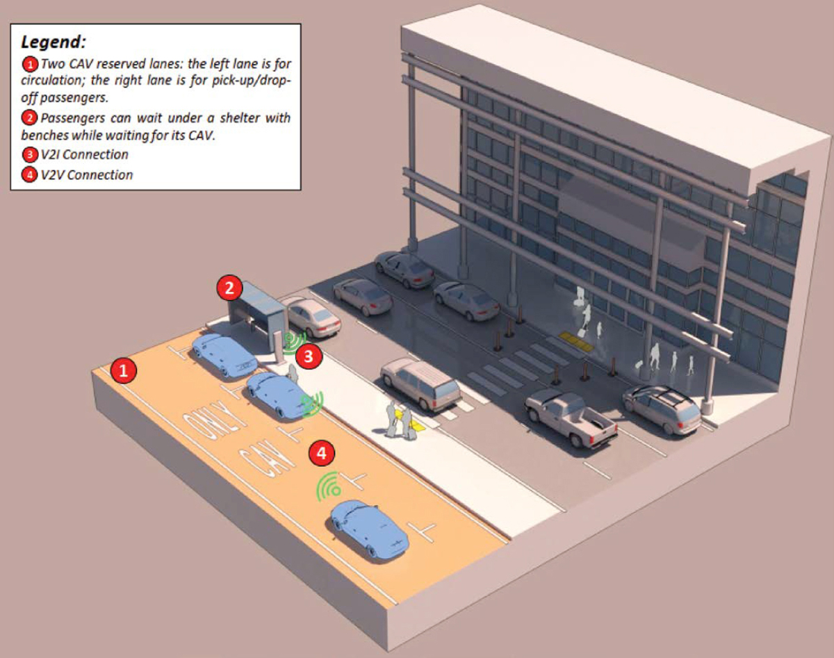
The existing road and highway infrastructure was developed to meet the needs and demands of human-driven cars without automation. As a result, modifications to lane width, road capacity, roadway markers, signage, and signalization may be necessary or opportune to accommodate or optimize roadways for self-driving connected and automated vehicles (CAVs) (Figure 58).
Lane Width and Road Capacity
Vehicle-to-vehicle (V2V) and vehicle-to-infrastructure (V2I) applications will enable smoother traffic by adjusting speeds to optimum levels according to the phase of traffic signals (Dennis et al. 2017). Vehicles will be able to follow other cars more closely while still being safe, improving throughput. Other benefits may include a reduced number of collisions, which now account for
Note: V2I = vehicle-to-infrastructure; V2V = vehicle-to-vehicle.
25 percent of traffic congestion, and possibly further advantages (Federal Highway Administration 2015).
Since CAVs can navigate more congested highway portions using lane-guidance technology without having to alter their speed or distance from other vehicles, lanes designated for only CAVs may not need to be wider to account for human mistakes. If vehicle dimensions essentially remain constant, lane width might be lowered by up to 20 percent to be closer to real vehicle width (Dennis et al. 2017).
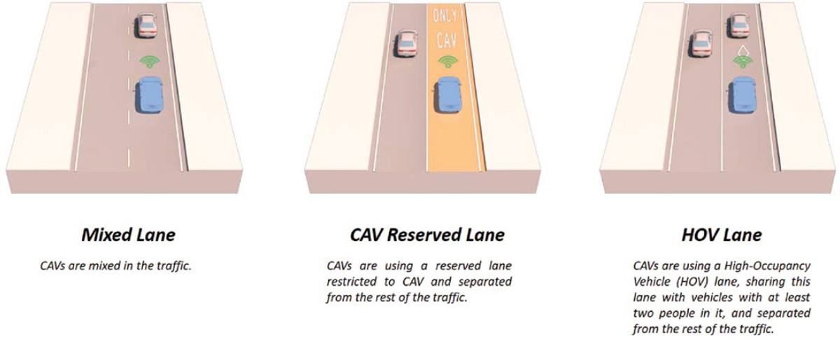
Furthermore, medians on CAV-only roads may be shortened or removed in the long term since there would no longer be a requirement for a safety buffer between traffic in opposing directions. Sidewalks, bike lanes, green space, and other uses for the conserved area might be considered. Figure 59 depicts the main CAV lane configurations.
Road Markings
With the use of machine learning systems, such as radars and cameras, some automated vehicles (AVs) rely significantly on identifying road markers. In order to maximize the effectiveness of lane departure prevention (LDP)—which prevents vehicles from drifting out of their lane—for currently available cars equipped with advanced driver assistance systems (ADAS) or automated driving systems (ADS), three factors for road pavement–marking areas have been identified: uniformity, design, and maintenance (Gopalakrishna et al. 2021).
Uniformity
The lack of pavement-marking uniformity throughout the United States is the most talked about issue from the automated vehicle sector when it comes to the highway infrastructure’s ability to accommodate these vehicles. U.S. highway authorities often follow the national Manual on Uniform Traffic Control Devices (MUTCD), but it is flexible enough to accommodate different approaches. Moreover, the MUTCD falls short in various respects, such as contrast-marking patterns, which can impact the effectiveness of LDP. Recently, the National Committee on Uniform Traffic Control Devices (NCUTCD) accepted certain proposed amendments to the MUTCD that were intended to tighten pavement-marking consistency across the country.
Design
As of June 2019, the NCUTCD CAV Task Force, in conjunction with AASHTO, Auto Alliance, American Traffic Safety Services Association, and the Automotive Safety Council, developed the following pavement-design recommendations that will support CAV technology as well as promote marking uniformity:
- Use 6-inch-wide longitudinal markings on freeways and interstate highways.
- Use 6-inch-wide edge lines on roadways with posted speeds under 40 mph.
- Use dotted edge line extensions along entrance and exit ramps.
- Include chevron markings in gore areas.
- Use continuous markings at the beginning of work zones and in all tapers.
- Eliminate the use of Botts’ dots (i.e., round, nonreflective raised pavement markers) as a substitute for markings.
- Use contrast markings on light-colored pavements.
- Use 15-foot-long lane lines with 25-foot gaps.
- Use only arrow shapes approved in the MUTCD.
Pavement markings must also be visible and identifiable in both dry and rainy situations, as well as during the day and at night. Pavement-marking visibility is typically seen as acceptable when the marking is present, especially under ideal circumstances like clear and dry weather. However, depending on brightness and pavement-marking contrast relative to the concrete surface adjacent to the pavement marking, LDP detection of pavement markings under daylight conditions—dry and wet—can be particularly difficult.
According to FHWA, key factors have been identified that will enhance the visibility of pavement marking. These factors include using markings that are
- Durable,
- High contrast,
- Able to maintain their colorfastness,
- Visible under wet conditions,
- Visible under glare conditions (certain sun angles), and
- Compatible with lidar technologies.
Maintenance
Although the development of minimum retroreflectivity requirements and maintenance for pavement markings in the United States is presently underway, these standards are meant to offer human-driven cars minimal visibility criteria; they are not explicitly made to accommodate ADAS LDP technology or future ADS road-perception technology demands. However, minimum maintenance requirements for pavement markings for LDP detection have been established by the European Union Road Federation. These requirements include
- Maintaining dry retroreflectivity to a minimum level of 150 millicandelas per square meter per lux (mcd/m2/lx),
- Maintaining wet recovery retroreflectivity to a minimum level of 35 mcd/m2/lx, and
- Maintaining contrast to a minimum level of 3:1, with a preferred level of 4:1.
Additional Methods to Keep Vehicles in Lane
Although road markers are essential to CAV operations, using lane markers alone to control automated driving is not a viable strategy (Dennis et al. 2017). Realistically, not all roads will always have lane markers in great condition. Therefore, CAV manufactures are investigating additional methods to keep vehicles in their lanes—such as placement in relation to vehicles, guardrails, and other objects with information from a variety of sensors and 3D maps—in order to develop a self-driving car capable of operating on any road at any time. Improving road
markings may be helpful to promote early adoption and increase the potential safety advantages of these vehicles.
An NCHRP research project is investigating pavement-marking performance parameters that may impact how well machine learning systems can read them (Pike et al. 2017). The findings from this study may help key stakeholders, including transportation officials, professional associations, members of the automobile industry, and owners and operators of infrastructure, to define the standards and rules for road markings.
Finally, NCHRP Research Report 891 (Booz Allen Hamilton et al. 2018) suggests that separation devices are not warranted between dedicated highway lanes shared with high-occupancy vehicles (HOVs) and general purpose lanes. However, separators should be considered with CAV-reserved lanes if the market penetration rate of these vehicles is low. While separation devices are not required under high market penetration rates, buffer-separated double solid lines may provide additional safety. This advice is based on an analysis using lane friction (difference of average speed) between the dedicated lanes and general purpose lanes as the performance measure.
Signage and Signalization
The functions of road signs and signals may be replaced with V2I communication and high-definition 3D mapping (Dennis et al. 2017). Vehicles may receive road indicators via cellular communication or dedicated short-range communications (DSRC). However, as signs and signals are still necessary for humans-driven cars, bicycles, and pedestrians, discarding them will not be a feasible option during initial stages. To support V2I applications, traffic signs may also need to be modified.
These applications could facilitate faster intersection crossing and better traffic flow, hence minimizing needless braking and accelerating. Another factor to consider for CAVs and signs are work zones on the road. Construction workers might use wireless beacons that send AVs instructions from a predefined list to reduce the likelihood of errors (Dennis et al. 2017). NCHRP Research Report 1051: Preparing Transportation Agencies for Connected and Automated Vehicles in Work Zones (Neurauter et al. 2023) provides further information on the expected impacts of CAV technologies on work zone environments. It features guidelines that prepare transportation agencies to support and expedite the implementation of these technologies in work zones.
Electric Charging Infrastructure
All-electric and plug-in hybrid vehicles use charging stations, called electric vehicle supply equipment (EVSE), to replenish their batteries’ power. EVSE can be available to the public or for private use (i.e., home charger), and these ports are not all created equal: Level 1 EVSE provides about 5 miles of range per hour of charge at 120V, while Level 2 EVSE uses 240V to replenish 25 miles of range in an hour. Recent EVSE also supports direct current or “fast” charging at 480V or greater, which can deliver more than 200 miles of range in 30 minutes; however, the connector technology offered at an EVSE port (Combined Charging System, CHAdeMO, or North American Charging Standard) might not be compatible with some battery-electric vehicles (BEVs) or plug-in hybrid-electric vehicles (PHEVs). Due to the substantially faster charge times, the share of public direct current “fast” chargers is steadily increasing, from 16.7 percent in Q4 2019 to 20.1 percent in Q2 2022 (Brown et al. 2022). While driving, electric vehicle range can be extended by up to 10 percent through regenerative braking, which transforms excess kinetic energy into electric energy that can charge the EV’s batteries (Chau 2014).
Electric vehicles will also challenge the energy grid locally in the midst of a general increase in electricity demand with the “electrification of everything.” While this warrants new investments in infrastructure for electricity production and distribution, demand vs. supply tensions might appear in the meantime. In the summers of 2021 and 2022, the California Independent System Operator—which oversees the operation of California’s bulk electric power system, transmission lines, and electricity market—issued a voluntary alert advising California residents to conserve energy to “help balance supply and demand” on the power grid during an extreme heatwave event (California Independent System Operator 2023). Unplugging electric vehicles during peak usage times was one measure among various recommended power-saving actions. In November 2022, the Swiss Federal Council issued a notice for proposed rulemaking proposing a federal power-saving plan in case of a national electricity shortage—in the context of the Russian aggression against Ukraine (Federal Council of Switzerland 2022). Stage 3 of the plan restricts utilization of private (i.e., personal) electric vehicles to trips that are absolutely necessary, such as professional obligations, groceries and medical appointments, religious attendance, and court orders. According to the impact assessment joined to the notice, a 6 percent energy savings is expected from all the restrictions on mobility (Département Fédéral de l’Economie, de la Formation et de la Recherche 2022).
Communications and Information Systems
Self-driving CAVs rely on a variety of communication systems to exchange information with other vehicles and infrastructure, as well as cloud-based, power grid, and other relevant connections. Some of the key communication systems used are
- Dedicated short-range communications: This is a wireless communication technology that allows vehicles to exchange information with other vehicles and roadside infrastructure at short ranges.
- Cellular networks: CAVs can also use cellular networks, such as 4G and 5G, to communicate with other vehicles as well as infrastructure. Unlike DSRC, cellular networks have a wider coverage area and can support a higher data rate. However, they are more vulnerable to congestion and signal interference.
- GPS: This is a satellite-based navigation system that provides precise positioning information to vehicles.
These communication systems are critical for the safe and efficient operation of CAVs. They allow vehicles to share information about their speed, location, and intended path, which can help prevent collisions and improve traffic flow. Furthermore, they will be equipped with the necessary firewalls and other security measures to safeguard the security and integrity of data transfer (Wishart et al. 2022).
Vehicle-to-Infrastructure
V2I refers to the communication between vehicles and fixed infrastructure, such as traffic signals, road signs, and weather sensors. V2I communication devices collect data generated by moving vehicles and wirelessly transmit alerts on environmental, mobility, and safety issues to the vehicle. State and local government organizations will likely build V2I infrastructure next to or integrated with current intelligent transportation system (ITS) equipment. ITS is a set of advanced technologies and systems that are used to improve the safety, efficiency, and sustainability of transportation. ITS equipment consists of
- Roadside units: These are devices installed along roads to provide communication and positioning services for CAVs. They use technologies such as DSRC and cellular networks to
- provide real-time updates about traffic conditions, road closures, and other relevant information to vehicles. As stated by the Federal Transit Administration (2015), according to FHWA, the unit communicates information such as
- – Red Light Violation Warning,
- – Stop Sign Gap Assist,
- – Reduced Speed/Work Zone Warning,
- – Curve Speed Warning,
- – Spot Weather Impact Warning, and
- – Pedestrian in Signalized Crosswalk Warning (Transit).
Roadside units (RSUs) can also be used to support the deployment of advanced traffic management systems, such as cooperative adaptive cruise control and platooning, which can help improve traffic flow and safety on the road.
- Traffic signal controllers: These are devices that communicate with vehicles and adjust the timing of traffic signals by generating the signal phase and timing message (green, yellow, red, and the amount of time left until the next phase) to the vehicles or RSUs.
- Traffic management center: These are facilities that use information from RSUs and other sources to monitor traffic conditions and optimize traffic flow.
Bus and BRT Systems
Overview
Both conventional bus and BRT systems are among the easiest mass transit systems to implement, since they can make use of existing roadways to operate. Conventional bus systems are associated with minimal necessary infrastructure (e.g., depots and bus stops), onboard fare collection, and nonexclusive operations along existing traffic lanes. BRT has adapted some of the features of LRT systems to improve service quality and average speed, such as using semi-exclusive or exclusive rights-of-way, larger stations with more amenities, off-board fare collection, and traffic signal priority (Federal Transit Administration 2015). This section presents facility requirements for both ground access modes while also highlighting mode-specific requirements.
Running Ways
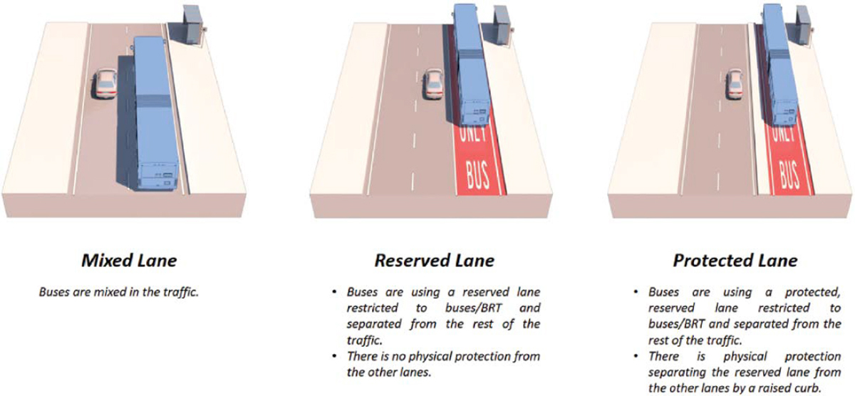
A key distinction between conventional bus systems and BRT is that running ways for BRT tend to separate its services from other ground transportation methods, thus increasing the system’s speed and throughput. These running ways can provide exclusive (Class I), semi-exclusive (Classes II–IV), and nonexclusive (Class V) rights-of-way, but running ways do not need to be of the same class system-wide. Since BRT running ways are designed to provide expedited flow for system buses and are not as affected by traffic congestion as other lanes, their usage can be appealing to non-BRT vehicles. Barriers and monitoring systems should be put in place to prevent the use of BRT facilities by unauthorized vehicles; penalties for misuse of BRT lanes should be high enough to dissuade unauthorized use. However, emergency vehicles should have access to BRT lanes when necessary. There shall be a minimum of two bus lanes (one for stopping and one for passing), each at least 11 feet wide but ideally 13 feet wide.
BRT systems are expected to perform better with Class I running ways, but these would require grade-separated infrastructure that would be more expensive to implement and would occupy a larger footprint; transit planners (including at airports) need to consider when and where these running ways would be cost-effective. Off-street, at-grade dedicated busways can also provide good BRT system performance. Off-street busways, if designed with sufficient corridor width, can be transformed into LRT rights-of-way should ridership demand require it. Introducing this kind of running way at airports as means of ground access would require additional roadways to separate BRT operations from other ground vehicles (Figure 60).
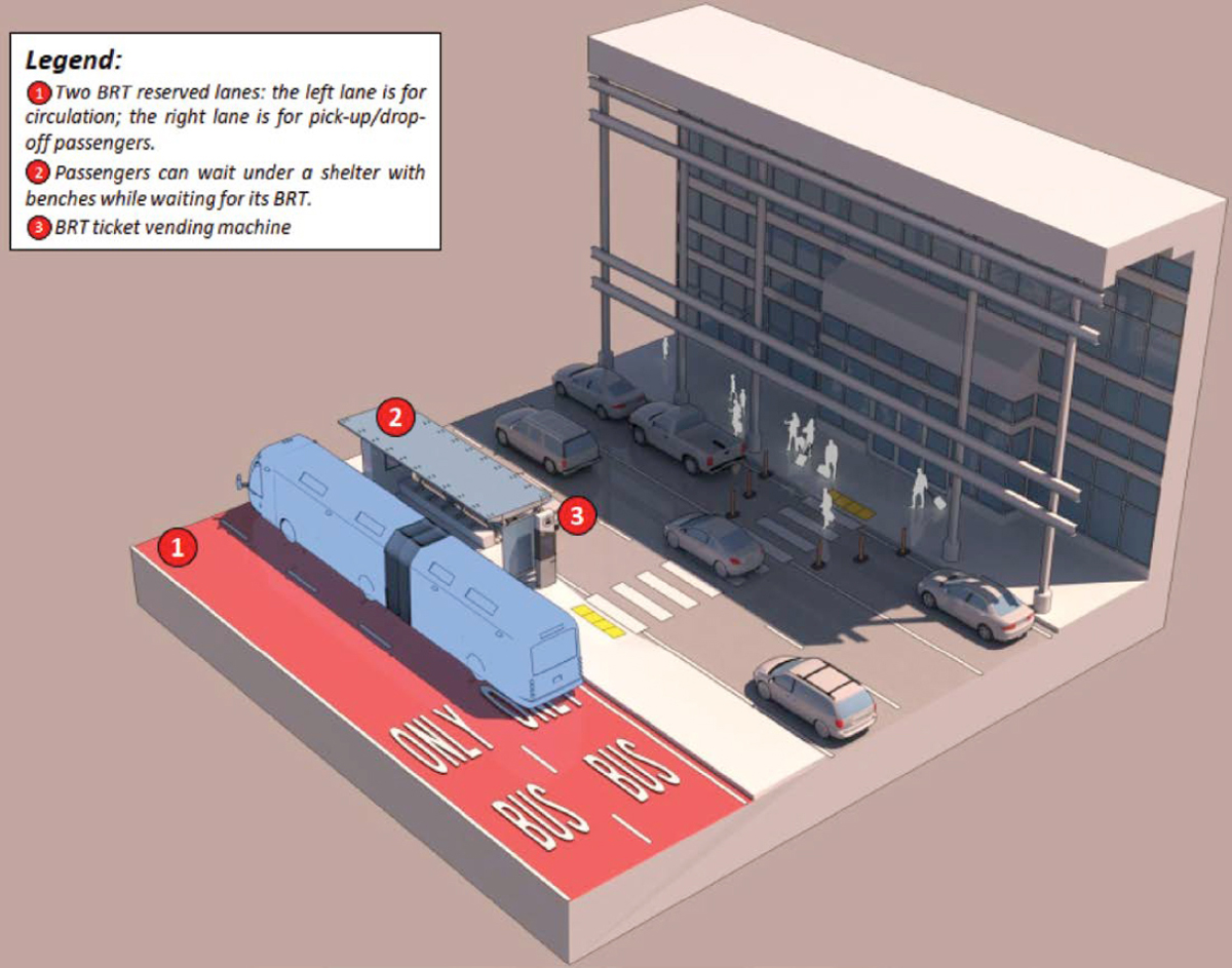
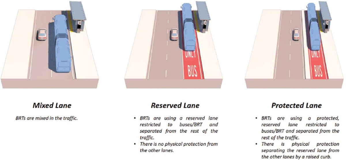
Off-street running ways might not be feasible in smaller or space-constrained airport environments, with BRT systems operating on the same streets as general traffic but with separate lanes and sufficient space for berthing (i.e., exiting the travel lane to collect and drop off passengers). These lanes should at least be clearly identifiable and distinguishable by using different pavement coloring or other signage, and barriers can be erected to separate BRT lanes from other traffic. To avoid curbside congestion, taxis, shuttles, and private vehicles should be loaded and unloaded on the opposite side of the road as BRT. Figure 61 and Figure 62 depict the main BRT and bus lane configurations, respectively.
System Operations
As is the case with most means of transport, one indicator of service reliability is delay—the difference between scheduled and actual times. Service reliability, among other factors, is directly correlated with ridership potential. TCRP Report 165: Transit Capacity and Quality of Service Manual, 3rd Edition (Kittelson & Associates, Inc. et al. 2013) divides causes for delay into two categories: delays at the bus stop and delays between stops.
Delays at bus stops are either intrinsic to the system’s operations or consequences of capacity being exceeded:
- Acceleration and deceleration into and out of bus stations.
-
Dwell time: time the bus spends loading or unloading passengers, including opening and closing doors. This timing is influenced by the number of passengers onboarding and alighting at each stop, onboard fare collection (or lack thereof), the number of doors available (e.g., in multi-door buses, passengers may board through the front door and alight through the rear one), and the need to accommodate passengers with reduced mobility (PRMs).
- – BRT improvements: on-station fare collection, multi-door fleets, accessibility.
-
Reentry and traffic signal delays: time during which the bus cannot advance while waiting for a green traffic signal or waiting to merge into the travel lane.
- – BRT improvements: semi-exclusive or exclusive running ways, traffic signal priority.
-
Boarding lost time: time spent by passengers finding the correct loading areas (only occurs at larger stops with multiple loading areas).
- – BRT improvements: line-specific loading areas, visual and aural announcement systems.
-
Bus stop failure: when buses are required to idle on travel lanes because all bus loading areas are occupied.
- – BRT improvements: real-time monitoring and metering.
Operations between stops can also be subject to delays, such as
-
Stop spacing: Reduced distances between stops leads to buses having lower running speeds or sustaining normal running speeds over shorter periods of time. However, reduced spacing between stops may be necessary in high-density areas where walking is the primary means of access.
- – BRT improvements: Stops are further apart; outside high-density areas, park-and-ride lots are used to encourage arrival by car.
-
Interaction with other traffic: Bus systems that run alongside other modes of transport can also be affected by road congestion or other delays.
- – BRT improvements: Exposure to other traffic is eliminated (grade-separated) or reduced (at-grade exclusive and semi-exclusive rights-of-way). BRT flow at at-grade exclusive and semi-exclusive sections can be further enhanced through signal control.
-
Stop location: On-street bus stops can be located immediately after crossing an intersection (far-side), immediately prior to crossing an intersection (near-side), and mid-block. Each of these can facilitate or hinder pedestrians, other buses, and general traffic; siting should be considered on a case-by-case basis.
- – BRT improvements: Stations can also be either grade-separated or off-street, which minimizes their effect on traffic flow.
-
Passing capabilities: A bus’s passing capabilities are its ability to change lanes to overtake an obstruction. Congestion or the lack of passing lanes can increase unnecessary idling times.
- – BRT improvements: BRT busways may include passing lanes.
- Near-saturation: Average bus speeds start decreasing at around 50 percent of lane capacity; these decreases become sharper beyond 70 percent due to inter-bus interactions and an increase in passing maneuvers.
TCRP Synthesis 110: Commonsense Approaches for Improving Transit Bus Speeds identified measures that can offset some of these delays, and these measures have led to a −0.45 percent annual change in average bus speeds nationwide. Some of these measures are design features of BRT systems that are now being implemented for conventional bus systems as well (Boyle 2014):
- Traffic engineering efforts to prioritize mass transit, such as signal priority and timing adjustments, bus-only lanes, and laws requiring yielding to buses.
- Maintaining transit routes along major corridors with few deviations and sharp turns, while also increasing distances between stops.
- Speedier boarding and alighting processes by using all doors that permit safe access to the bus and changing to prepaid ticketing models.
- Deployment of low-floor buses with ramps to reduce the time required by PRMs to safely board.
- Requiring buses to hold at stops when ahead of schedule, as well as optimizing schedules based on historic delay data and projected changes in ridership volume.
Automated Buses
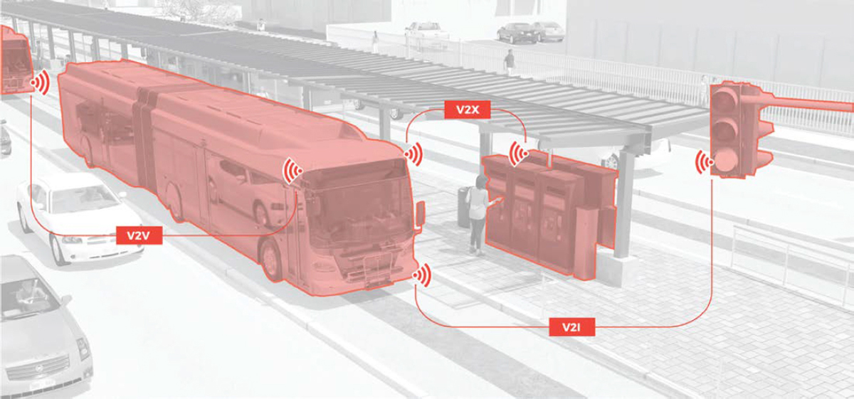
Bus systems and other non-guided ground vehicles could potentially be automated by introducing connected vehicle technologies that are already available in private vehicles with SAE Level 2 technology (e.g., adaptive cruise control, lane keeping, speed adjustment in curves, and stopping for pedestrians and vehicles) and incorporating vehicle-to-everything (V2X) communications with roadway and station infrastructure, as shown in Figure 63.
Implementing platooning—multiple automated buses traveling in single file within close proximity while using internal technologies, such as radar, lidar, and cameras, or connected technologies, such as V2V communications, to keep a safe following distance—can maximize bus lane utilization and increase system capacity. At stops, automated driving technology would allow buses to pull into, stop at, and exit from precisely defined loading areas; automated passenger counting technologies can also be used to track load factors and enforce vehicle capacity constraints. The increased capacity achieved by platooning might translate into requirements for longer station-boarding areas (WSP 2022a).
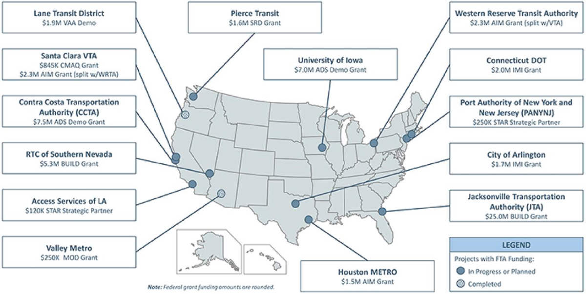
Adoption of automated buses will require testing to prove these vehicles’ safe operating potential to transit operators, potential riders, and the general public. To that end, the FTA is funding several pilot and demonstration programs across the country, as depicted in Figure 64.
Source: WSP (2022a)
Source: Federal Transit Administration (2021)
Note: AIM = Accelerating Innovative Mobility; BUILD = Better Utilizing Investments to Leverage Development; CMAQ = Congestion Mitigation and Air Quality; IMI = Integrated Mobility Innovation; MOD = Mobility on Demand; SRD = Safety Research and Demonstration; VAA = Vehicle Assist and Automation; VTA = Valley Transportation Authority; WRTA = Western Reserve Transit Authority.
Abroad, Scotland’s CAVForth program started revenue service demonstrations on a 14-mile bus line operating under SAE Level 4 automation in May 2023 (CAVForth 2023).
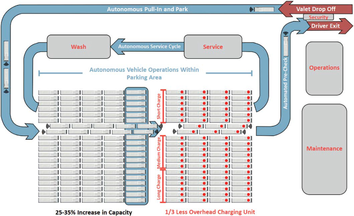
Benefits are also expected at yard facilities. Inside an automated bus yard (ABY), buses move in automated mode through the bus wash, charging stations, maintenance bays, and parking locations as necessary, as shown in Figure 65. Besides improving safety for bus yard personnel, these operations provide transit operators and bus manufacturers with continuous opportunities to verify operational safety and resolve issues that might be identified during the testing process (WSP 2022a).
Station Design
Station design for bus and BRT systems depends in part on the running way that the system will use at the station site and on the square footage available for station placement. Curbside platforms should be at least 10 feet wide and island platforms should have a minimum width of 20 feet to comply with ADA Accessibility Guidelines (ADAAG). Platforms should also be wide enough to accommodate 15-minute peak affluence for a planning horizon of 5 to 10 years. Both buses and platforms must be at an adequate height that allows easy ingress and egress for PRMs. Pedestrian crossings can be grade-separated or at-grade, with stoplights controlling traffic flow for the latter.
The simplest and least expensive implementation of a passenger loading area involves buses stopping on the travel lane closest to the bus stop to serve it. This approach leads to a linear loading area where buses follow a first-in, first-out sequence; buses cannot leave the station
Source: WSP (2022a)
until the bus ahead has done so. A variation of this is the “bus bulb,” where a section of the curb otherwise used for parking or pedestrian movements is reserved for buses to board and alight without impeding the flow of traffic in travel lanes. BRT stations and larger bus stops are more likely to use nonlinear loading areas, where buses will park in delineated locations outside traffic lanes and at an angle to them, allowing freer access between the travel lane and the loading area. Germany conducted research and development of docking guidance concepts where rail-like features guide buses into and out of the loading area to minimize the gap between the bus and the platform, facilitating access to the bus for PRMs and passengers with luggage or strollers (Leigh Fisher Associates et al. 2000).
BRT is characterized by an increased LOS relative to conventional bus systems, including additional infrastructure for passenger safety and security. “Sheltered” waiting areas, with at least one wall—and preferably three—are expected to provide passengers with protection from winds and precipitation while waiting for their bus. The walls in these waiting areas should be transparent to allow passengers within the waiting area to see outward, and vice versa. Basic facilities, such as trash bins, should be provided.
For BRT systems, fare collection is carried out at the station—not onboard the bus—to reduce boarding times from 2–5 seconds per person for on-bus fare collection to 1.75 seconds per person for off-bus collection (Kittelson & Associates, Inc. et al. 2013). Kiosks can be made available for single-ticket or ridership card acquisition and to reload ridership cards. Tickets can also be purchased through authorized mobile apps that use QR codes or near-field communication for pass validation. Enforcement of fares is possible through physical barriers that limit access to only riders with valid tickets. However, this strategy requires additional infrastructure investments and additional floor space to separate the boarding area from the rest of the station. An alternate strategy involves random inspection of tickets by system staff onboard the bus, which entails additional manpower and operating costs.
Bus signage should be consistent along the transit system. While states and municipalities may have their own standards—such as the North Carolina Department of Transportation’s Bus Shelter & Bus Stop Guidelines (2017)—they are expected to meet the criteria in the MUTCD. Stops should be clearly identified by name and include route maps for the bus lines serving them, connection information, and route frequencies. If specific bus lines stop at different loading areas, this should also be indicated to prevent boarding lost time. Signage should allow for progressive wayfinding (i.e., turn-by-turn guidance, when not obvious), be illuminated in low-light conditions, and be accessible to people with visual disabilities (e.g., braille or other haptic aids, differentiated pavement textures, color palettes distinguishable to people who are color-blind, aural announcements). Display boards indicating next arrivals and corresponding loading areas should also be provided, if possible (National Association of City Transportation Officials n.d.).
Implementation at Airports
Travelers using bus systems to and from airports are likely to arrive at bus stops and stations by foot. TCRP Report 90: Bus Rapid Transit, Volume 2: Implementation Guidelines (Levinson et al. 2003) states that BRT stations are typically spaced between ¼ and ⅓ of a mile apart from each other. Smaller airports might only require one station, but airports with longer curbsides or multiple terminals should consider implementing multiple stations. At the same time, stations should be spaced far enough to reduce trip times and maintain high operational speeds.
One specificity of airport bus riders is that they are more likely to travel with luggage than riders who commute by bus. This creates line-specific design challenges that would require level entry into buses (either by low-floor or elevated platforms, or a combination thereof) to reduce dwell times associated with riders carrying luggage up and down steps. Level entry would also
improve ADA compliance within these systems. Luggage storage options should also be provided to prevent passenger luggage from occupying or blocking access to otherwise open seats (Leigh Fisher Associates et al. 2000).
Signage between bus or BRT stations and airport terminals should provide clear wayfinding from the station to the airlines’ check-in desks as well as from the baggage claim areas to the station, following the parameters described in the previous section on station design. The airport terminal signage may have a different yet standardized appearance that is also inspired by the MUTCD. Icons and nomenclature between signage for the airport and transit systems should be consistent to avoid confusion (Harding et al. 2011).
Heavy Rail
Corridor
Heavy rail is characterized by fully grade-separated rights-of-way; high-level platforms; and high-speed, electric multiple-unit cars (Kittelson & Associates, Inc. et al. 2013). Unless grade separation is achieved through an elevated structure, tunnels, or wall above 6 feet in height, the right-of-way should be fenced because heavy rail transit systems should prohibit all access to their rights-of-way. Basic security fencing includes chain link fence that is at least 6 feet high and other fences that provide similar or improved intrusion protection. Access to the right-of-way should be controlled by locked gates (American Railway Engineering and Maintenance-of-Way Association 2021).
Based on project examples provided by the FTA and manufacturer specifications, consolidated by the Florida Department of Transportation Office of Freight, Logistics, and Passenger Operations, an average corridor width of heavy rail is between 25 and 33 feet. The average corridor width does not include space for stations or potential widening at turns. Additionally, unlike other types of passenger rail, heavy rail is unable to operate on freight tracks per restrictions by the Federal Rail Administration, eliminating the possibility for a shared corridor between heavy rail transit and freight rail systems (Florida Department of Transportation 2017).
Right-of-Way
Right-of-way is the term for all property interests and uses necessary to build, maintain, safeguard, and run a transportation system (Skanska 2013). Some right-of-way requirements are temporary, while others are permanent and driven by operational requirements. The following are guidelines for determining the right-of-way limit according to the Metro Rail Design Criteria (Skanska 2011):
-
Underground (below grade):
- – Upper limit: The upper limit is the vertical distance between the top of the rail line and the object or structure above; and 10 feet is the minimum requirement for the vertical distance.
- – Horizontal limit: The horizontal limit is a lateral distance of 5 feet (for earth tunnels) or 10 feet (for rock tunnels) from the surface of the tunnel. Allowances shall be made for rock bolting or grouting, which may be required.
- – Lower limit: Lower limits are usually not applicable to underground rail systems.
-
At grade:
- – Upper limit: An upper limit is usually not required for at-grade rail lines. When required, the minimum distance between the top of the rail line to the upper surface should be 16 feet, 6 inches.
-
- – Horizontal limit: The following conditions determine how far the nearest track’s centerline must be from the right-of-way limit when using an exclusive right-of-way:
- With walkways outside of the track, utilize the dynamic envelope of the rail car, the horizontal track construction tolerance on both tangent and curved alignments, as well as the individual state’s Public Utilities Commission minimum clearance standards.
- With walkways between the tracks, utilize the dynamic envelope plus the running clearance of the rail cars as well as the horizontal track construction tolerance.
- – Lower limit: Lower limits are usually not applicable to at-grade rail systems.
- – Horizontal limit: The following conditions determine how far the nearest track’s centerline must be from the right-of-way limit when using an exclusive right-of-way:
-
Above-grade:
- – Upper limit: Similar to at-grade rights-of-way, the minimum distance from the top of the rail line, when required, to the upper surface should be 16 feet, 6 inches.
- – Horizontal limit: The horizontal limit is a lateral distance of 25 feet from the track’s centerline. For the upkeep and repair of structures, easements would be required.
- – Lower limit: The lower limit shall be the ground level, with particular usage limits when they are necessary due to local conditions and as ordered by state or county, with the exception of when crossing other rights-of-way.
Signal and Communication Systems
A heavy rail signal and communication system involves many or most of the same components as for other rail systems. A heavy rail system should operate with an automatic train control (ATC) system in place, which is “designed to address train safety, control train operations, and direct train movements on the main line and in the yard” (Skanska 2013). System design objectives should include safety, operational efficiency, cost-effectiveness, and upgradability.
The ATC system includes four major subsystems, according to the 2010 Metro Rail Design Criteria (Skanska 2013):
- Automatic train protection (ATP) enforces speed restrictions when actual speed is greater than maximum safe operating speed for any given section of track. Speeds are transmitted to the train through either track circuits or wire loops from the wayside equipment.
- Automatic train supervision controls and directs train movements on the main line and in the yard. This subsystem monitors train operation and provides controls, indications, automatic route initiation, and automatic dispatching to maintain the intended traffic patterns and operations schedule.
- Highway crossing warning system (HCWS) provides an interface between the wayside signal equipment and the crossing warning devices. The interface between the two should provide timely information about, and protection from, an approaching train.
- Train-to-wayside communication system communicates between trains and vehicle equipment or wayside interrogators at appropriate points along the route. Information communicated may include vehicle identification, routing information, establish or cancel routes, and activate or deactivate HCWS.
As noted previously, the systems should be designed for upgradability, which includes building for easy expansion of the system should future needs outpace existing infrastructure or should future upgrades to the existing system be required. As such, ATC subsystems should be developed as a building block design with minimal modifications at the outset so they can be modified or added to with minimal complications.
Stations
Heavy rail systems use platform stations, and typical spacing is less than 1 mile between stations for heavy rail operating within a city and 1–5 miles or more between stations for heavy
rail operating in the immediate suburbs (Florida Department of Transportation 2017). Any planning for an underground or elevated system should consider the potential for future growth since these stations, located above or below grade, are difficult to lengthen once constructed.
Site Development
To begin site planning, factors such as existing building relationships, future joint developments, as well as ethnic and cultural characteristics of neighborhoods should be considered.
Accessibility
The design must adhere to all applicable accessibility requirements, such as ADAAG, published by the FTA. As far as practicable, all accessible entrances must be similar to those utilized by the majority of the general public. Signage that complies with ADAAG requirements must be provided to identify and lead people to the accessible entry and route if the circulation pattern is different. Platform barriers must be available and meet ADAAG standards.
Entrances
- The following factors must be considered when designing a station’s entrance:
- – For the convenience of the public—especially passengers—as well as for operational and maintenance needs, entrance designs must maintain a clear, highly visible, and unique identity.
- – Provide direct and safe pedestrian access.
- – Entrance canopies must be provided to offer weather protection.
Circulation
- When designing passenger circulation, encourage a “user friendly” mindset, with simplicity of use and easy route identification. These factors should also be considered when designing passenger circulation:
- – People tend to keep to the right, thus right-hand flows are recommended, although not mandatory.
- – Any crossflow of passengers is highly undesirable, and the layout should ensure that passenger flows moving in the opposite direction will be separated at all times.
- – Dead-end conditions shall be avoided wherever possible.
- – Whenever there is more than one opening, people tend to move toward the nearest one, even if they are not sure whether it is the right one.
- – People will tolerate longer delays in entering than exiting stations, but designs of stations should attempt to eliminate waiting.
- – Circulation patterns and station layouts should enable passengers to know where they are and where they are going at all times.
- – Queuing distances shall be maintained at all stations to promote and guarantee ease in circulation and access to trains.
Platform Configuration
Station platforms are designed for the longest train that the system plans to operate, which optimizes the flow capacity of the train doors. For station platforms that are shorter than the train length, passengers must exit and enter from selected cars at the beginning or end of the train, which is not desirable practice and is atypical for new systems (Kittelson & Associates, Inc. et al. 2013). To meet ADA requirements, platforms should have tangent (straight) edges and the surface of the platform level with the train vestibule. Additionally, there should be no more
than a 3-inch gap between train door and platform edge. Space planning for platforms should include space for boarding passengers to queue and space for alighting passengers to exit the train to transfer to vertical circulation elements. The following factors must be considered when designing a station’s platform:
- All platforms, whether center or side platforms (depending on traffic conditions, site constraints, or layout of station), should be raised.
- All platforms should have a 24-inch safety edge.
- Freestanding columns within 10 feet of the platform edge shall be located away from vehicle doors during station stops to minimize congestion.
- Platforms should accommodate the peak 15-minute departing passenger volume at 10 square feet per person or the peak 15-minute departing and arrival passenger volume at 7 square feet per person.
- The warning line or “stand behind” line shall be drawn or embedded into the platform.
Concourse
The concourse serves as a passageway between the station’s entrance and access points to the train platforms. Additionally, the concourse also serves as a location for a number of conveniences for passengers, such as fare gates, passenger waiting areas, concessions, and other amenities. Concourses can either extend the full length of the station or occupy a portion of the station.
Station Dwell Times
As a factor in operational efficiency and a typical primary factor in the number of trains that can operate at a time, station dwell times are an important component of the system to consider. According to TCRP Report 165 (Kittelson & Associates, Inc. et al. 2013), factors affecting dwell times include
- The volumes of passengers boarding and alighting from trains during peak hours;
- The physical configuration of the platform: its width, length, curvature, usable area for passenger queuing and circulation, and configuration and capacity of vertical circulation;
- The rate at which passengers alight from and board the train;
- The extent of any horizontal gaps between train door sill and the platform edge or differences in elevation between the platform and the car floor, which affect the rate at which passengers board and alight;
- The time required to open and close the train doors; and
- Operational procedures affecting the boarding process.
Support Facilities
Zoning for support facilities, such as shop and yard facilities, should ideally be light industrial and located away from residential neighborhoods. Support facilities generally take on a rectangular shape for buildings, thus the most desirable siting parcel would be either rectangular or trapezoidal. Land for yards and shops needs to “accommodate car storage tracks, inbound service and inspection tracks and shop buildings” and should allow sufficient width to provide a turning loop on the property (American Railway Engineering and Maintenance-of-Way Association 2021). A list of facility functions that are needed to support rail transit are provided in American Railway Engineering and Maintenance-of-Way Association’s (AREMA’s) 2021 Manual for Railway Engineering.
Implementation at Airports
According to TCRP Report 62: Improving Public Transportation Access to Large Airports (Leigh Fisher Associates et al. 2000), for airports the main elements of a successful airport rail system are
- Service to downtown metropolitan area: For an effective and efficient rail service to the downtown area, focusing on either rail line speed from downtown to the terminal and vice versa or the quality of services as well as limiting the headway caused by joint operation with other regularly scheduled services should be priorities. Both approaches aim to generate a door-to-door travel time that rivals that of a taxi or a private automobile.
- Service to national destinations beyond the metropolitan area: Most airport rail connections to national destinations are integrated with other rail services and are not provided by a special dedicated service. The size of the national rail network into which an airport has been linked is crucial because the lack of such a network will make these initiatives difficult or impossible.
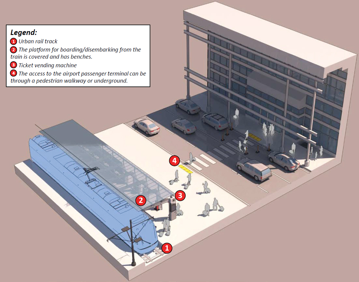
- Quality of rail connections at the airport or airport-railway interface: Important considerations to ensure a quality rail connection are the quality of service offered by the train, the quality of the boarding experience, and the quality of the experience when connecting to other modes to reach the final destination. Another relevant factor is the ease of finding the rail station and the seamlessness of the connection to that rail platform. A high level of collaboration between the rail system designer and the airport designer is frequently necessary to create a high-quality, multimodal transfer facility (Figure 66).
-
Baggage-handling strategies and off-site facilities: For all designers and developers of airport ground access systems, developing a plan to address the issue of baggage is a challenge. Various solutions to the issue have been developed, ranging from making minimal changes to building expensive, full-service, off-site check-in facilities. However, a number of less expensive options are being tested globally. Off-site baggage-handling services can be divided into two main groups:
- – Full-service downtown check-in locations: This service is based on the idea that airlines will offer complete check-in services, including issuance of airline tickets and accepting luggage at off-airport rail stations. These services are performed by airline personnel.
- – Nationwide programs to handle numerous off-site check-in options: Instead of individual airline personnel staffing the baggage-handling services at off-site locations, a third party is employed to handle all baggage check-in services nationwide at all off-side facilities.
Light Rail
Trackway and Vehicle Compatibility
When determining how and where to position rail tracks, several design components need to be considered. Track grading needs to be shallow enough to allow vehicles to ascend under their own power and to descend without applying excessive loads on braking systems. Conversely, tracks also need to be steep enough to allow drainage to occur, unless alternative means to do so are provided. For LRT systems, TCRP Report 155: Track Design Handbook for Light Rail Transit, 2nd Edition proposes a maximum sustained grade of 4.0 percent without distance limitations, which can be increased up to no more than 9.0 percent or the vehicle’s operating limitations (whichever is less) for shorter distances; a minimum grade of 0.5 percent is also recommended (Parsons Brinckerhoff, Inc. et al. 2012). These requirements have been incorporated into the design codes for local LRT projects, such as Sound Transit’s project in the Seattle metropolitan area (Sound Transit 2021).
LRT is unique among urban rail systems in that it may operate at-grade along city center streets, thus it can be constrained by the geometry of streets and adjacent land use (buildings, parks, etc.). A minimum turn radius for horizontal tracks of 82 feet is recommended; this is derived from European practices, which accommodate usual train car lengths and widths. This is not a formal standard—manufacturers have developed cars with turn capabilities as low as 42 feet, and transportation agencies in Philadelphia, San Francisco, Boston, and elsewhere have permitted tighter curve radii (Graebner et al. 2007). Consecutive curves in opposite directions (reverse or “S” curves) need to be separated by a minimum length of straight track to remain within wheels’ performance envelope and to avoid passenger discomfort. LRT vehicles can be designed to be articulated to improve their handling, but the functionality improvements are related to the length of the articulation—longer articulations result in smaller improvements in minimum turn radii. Speed limits are set to keep lateral acceleration below 0.1g (g = gravity of Earth), which is considered the maximum acceleration that can be comfortably experienced by riders; in curves, this also accounts for the effects of superelevation, a difference in elevation between the outer and inner rails in a turn that can neutralize centripetal acceleration forces (Parsons, Brinckerhoff, Quade and Douglas, Inc. 1999).
A typical modern LRT vehicle is approximately 82 feet long, 9.5 feet wide and runs along straight tracks (articulated vehicles’ effective width may increase up to 11.7 feet during turns). Vehicle cars also have a street-to-ceiling height of approximately 11.5 feet, not including current collector systems (National Association of City Transportation Officials 2016). The most demanding physical parameters that govern the dimensions and configuration of the train’s rolling stock are the system’s tracks.
Right-of-Way
The MUTCD specifies that LRT systems can have either exclusive, semi-exclusive, or mixed-use rights-of-way (Federal Highway Administration 2023). Exclusive rights-of-way can be attained by grade separation (through underground or elevated tracks) or barriers to control access (fences, traffic barriers, or a combination of both). In the rights-of-way for LRT systems, neither motor vehicles, pedestrians, nor bicycles are allowed. Semi-exclusive rights-of-way allow access for motor vehicles, pedestrians, and bicycles but only at crossings and designated locations, while mixed-use rights-of-way allow other traffic to operate alongside it. Exclusive and semi-exclusive rights-of-way are more likely to exist outside of downtown areas, while mixed-use rights-of-way may become necessary within downtowns due to street space limitations.
When LRT systems operate in semi-exclusive rights-of-way, the MUTCD calls for implementation of traffic control systems to prevent unauthorized incursions when a trainset is passing. These systems can consist of aural and visual alerting systems and movable barriers. Implementation of these systems needs to be carried out on a case-by-case basis that accounts for the specificities of each crossing (Federal Highway Administration 2023). When planning rights-of-way, consider drivers’ and pedestrians’ habits: Longtime residents might not register the changes in rights-of-way early in the implementation process, which could lead to not noticing traffic control devices and potentially result in collision situations.
LRT systems generally require a minimum running clearance of 2 inches, applied horizontally, from other obstructions and vehicles; these clearances increase to 6 inches along aerial decks and between LRT vehicles. Vertical clearances are predicated on a margin between 4 and 6 inches from the clearance envelope, including the effects of superelevation (Parsons, Brinckerhoff, Quade and Douglas, Inc. 1999). LRT operations in mixed-traffic conditions should take place in lanes that are at least 11 feet wide for straight segments; additional width shall be provided for curved tracks to accommodate the train’s envelope. For LRT systems that operate with overhead power, catenary wires are located between 17 and 20 feet above street level; these need to be kept clear of other tall features (e.g., trees and traffic signals) and not hinder traffic signal visibility (National Association of City Transportation Officials 2016). Rolling stock, whether purchased, leased, or remanufactured, must be accessible to and usable by individuals with disabilities, as mandated in 49 Code of Federal Regulations (CFR) Part 37, Sections 79, 81, and 83.
Stations
Rail infrastructure requirements are more restrictive at stations than along the transit corridor to ease passenger boarding and alighting and to comply with ADA requirements: Track grades should be between 0.5 and 1.0 percent at stations, compared to 4.0–9.0 percent elsewhere. LRT platforms, like those of other mass transit modes, should be sized relative to the estimated peak 15-minute affluence of the station—offering at least 15 square feet of waiting room per person. Sound Transit’s standards recommend that platforms should have at least 380 feet of available length for boarding and alighting a four-car train.
Platforms can be either centered (island) or on the side; the decision of which type to build should be based on expected peak affluence and integration with the urban environment
(streets and other transit systems, such as BRT), with the ultimate goal of improving system efficiency. At-grade platforms’ minimum widths vary according to their configuration: Center platforms should be at least 20 feet wide, while side platforms should have an edge-to-wall width of no less than 12 feet. Neither columns nor walls should be placed within 8 feet of the platform edge since these could interfere with the safe operation of train doors; station components such as vertical circulation nodes can encroach onto the platform width if this width is never reduced below 8 feet. The 2 feet area closest to the platform edge should have haptic aids (dome pavers) to comply with ADA requirements; passengers should not wait in this zone. To facilitate drainage, platforms should have a 1 percent cross-slope toward the trackway. Like other means of transport, LRT stations should also have three-walled, roofed shelters or windscreens to protect waiting passengers during weather events.
Because LRT stations might be placed at-grade among dense city streets, unlike heavy and commuter rail, reduced available station space might preclude the placement of fare gates and their division of station space into free and paid areas. Rather, LRT systems are more likely to operate on proof-of-payment, where train access is not controlled but manual ticket inspection takes place onboard; this option is also more feasible due to the smaller vehicle size and thus lower personnel requirements.
Implementation at Airports
TCRP has described the factors involved in developing a successful rail system at airports, which also concerns LRT. Integration of LRT at airports might be suitable at airports where the forecasted ground access ridership is too large for BRT service to operate but too low for heavy or commuter rail systems. Since right-of-way and platform requirements between BRT and LRT have some similarities, airports could receive BRT services initially and then switch to LRT as passenger demand increases. At-grade LRT can also be integrated into the airport’s roadway system, minimizing construction costs.
However, there might be situations where running LRT systems at-grade is not efficient and grade-separated rights-of-way would be necessary, such as the Seattle-Tacoma International Airport (SEA) station. At this station, elevated rails near the airport and its runways could become obstacles to air navigation, so land use coordination with the airport is imperative; and transit planners should be open to rerouting the LRT’s tracks or reducing the track elevation, or both.
As is the case with other modes of ground access, signaling should be standardized, and routing to and from the airport terminal needs to be simple and unambiguous.
Commuter Rail
Corridor
Since building new infrastructure is cost prohibitive, commuter rail typically runs on a shared corridor with freight railroads. According to the American Association of Railroads (2023), half of all commuter systems operate at least partially on freight-owned track. Typical maximum operating speeds range from 60 to 90 mph (97 to 145 kilometers per hour [km/h]) with average speeds between 20 to 45 mph (32 to 72 km/h), depending on the route length, number of stations, and types of service. The Federal Railroad Administration’s Highway-Rail Grade Crossing Guidelines for High-Speed Passenger Rail mentions that “for speeds less than 80 mph, standard and supplemental safety devices should be used to maintain safety at highway-rail grade crossings along lines used for passenger systems” (Federal Railroad Administration 2009b). Table 24 is a summary of highway crossing guidelines for various passenger-rail operations based on operational speed.
Table 24. Summary of Grade Crossings for Passenger Rail
| Commuter Rail | Emerging High-Speed Rail | High-Speed Rail Regional | Additional High -Speed Rail | |
|---|---|---|---|---|
| Max Speed | 0–79 mph (0–127 km/h) | 80–110 mph (129 –177 km/h) | 111 –125 mph (179 –201 km/h) | >125 mph (>201 km/h) |
| Public Highway-Rail Grade Crossings, Generally | Automated warning: supplementary measures were warranted | Sealed corridor; evaluate need for presence detection and positive train control (PTC) feedback | Barriers above 110 mph (129 km/h), see 49 CFR § 213.247; presence detection tied to PTC above 110 mph (129 km/h) | None above 125 mph (201 km/h) |
| Private Highway-Rail Crossings, Generally | Automated warning or locked gate preferred; crossbuck and stop or yield sign where conditions permit | Automated warning with gates or locked gates (interlocked with signal system at higher speeds) | None or as above | None above 125 mph (201 km/h) |
Right-of-Way
Per the NorthStar Commuter Rail Project Design Criteria (Kimley-Horn and Associates, Inc. 2006), the following guidelines are provided for determining the right-of-way:
- Fixed obstructions greater than 8 inches above top of rail shall be a minimum of 15 feet from track centerline, except where an exemption is agreed on.
- Along the main line, a minimum of 18 feet from track centerline to track centerline (double tracks) shall be maintained, except where the relevant authority grants an exemption.
- In the station areas, a 15-foot center-to-center distance with inter-track fencing and concrete ties extending 100 feet from the end of the platform shall be standard.
- Maintain a minimum of 23 feet overhead clearance from top of rail to a fixed overhead obstruction.
- No landscaping except turf grass and ground covers is allowed within 25 feet of track centerline (exemptions can be made for small-leaf trees separated from the tracks by intervening buildings), and landscaping must not impede visibility at grade crossings. Provision must be made for removal of runoff from the track area.
- A walking surface is to be provided and maintained along both sides of every railroad track. It extends 8 feet, 6 inches from track centerline.
Rolling Stock
The two most common types of commuter rail trains are diesel-powered trains and electric-powered trains that run on tracks with electric overhead catenary wires or third rails. In the United States, commuter rail trains typically consist of a single locomotive and several passenger coach cars. Depending on the train’s capacity, a commuter rail trainset typically has three to eight cars that are either single- or bi-level. Approximately 115 persons can sit comfortably in single-level coaches. Bi-level coaches may accommodate about 180 passengers and include seats on two separate levels.
- Locomotive equipment: Locomotive trains have a powered rail vehicle that is used to pull the whole train. For commuter trains, this vehicle could be powered by either electricity or a diesel engine (earlier forms used steam).
- Multiple-unit equipment: Multiple-unit trains have individually powered cars or carriages, also known as self-propelled vehicles. This means each car or carriage has a motor (traction electrical motor or diesel generator) that is controlled by a single system and driver. With multiple-unit systems, there can be a dedicated cab car or every car can be equally equipped with a driving console (meaning any car can be used as a driving cab).
Signal and Communication Systems
Because commuter rail agencies typically seek to use existing infrastructure that is primarily owned by private freight railroads, the communication and signal infrastructure is already installed for use. Commuter, intercity, or high-speed rail share the following signal and communication system considerations:
- Essential communications include communication between moving trains and wayside stations and control centers, as well as track-to-train communications. Moving-train-to-station communication includes both digital and voice radio and extends to dispatcher and train crew communications as well. Digital data links are used to transmit data between moving trains and control centers, including transmission from moving train to wayside station to control centers via radio over fiber optic cable, microwave, ultrahigh frequency, or very high frequency radio station segments. Track-to-moving-train communication uses inductive communication technology via a beacon, inductors, or transponders. Coded track circuits in the rail assets also transmit signaling data, speed commands, and more to the train cab, while systems that do not use coded track circuits can use digital radio links.
-
Onboard communications
- – Various visual signs, including station announcements, are required by federal regulation to aid disabled passengers.
- – A public address system is essential to keep passengers informed of the train’s progress and provide service and station updates. It may be advisable to have voice radio via portable handsets for crew member communications and an onboard conductor’s station with a 30-to-50-watt output radio to facilitate contact with the control center or local dispatcher. Suitable locations for a conductor’s station include the dining car and other mid-train options. The conductor’s station should be powerful enough to reach a wayside base station.
-
Emergency communications
- – Batteries should be provided for the 30-to-50-watt radio to enable crew members to contact the control center and local emergency services. The radio communications load should be considered when sizing battery power for cars and locomotives.
- – Good, clear, prearranged, interference-free, and reliable communications to local fire and police departments should be in place along a high-speed train route to ensure quick response to emergency situations.
- Wayside and onboard defect detection—communication links between trains and wayside detectors, including hotbox, hot wheel, cracked or broken wheel, and dragging equipment detectors—should be in place on high-speed rail lines. Voice communication to crews may be instituted so crew members are continually updated on threats, or the lack thereof, on the line and can proceed along the route. Defect data is usually transmitted to a central command, and some railroads find it helpful for all hotbox detector readings to be sent to central command. Locomotive system monitoring is important for high-speed operations, and a data link may be used here since it should have sufficient capacity to transmit data to and from trains.
- Enhanced passenger communications may include public telephone service at phone booths, radio or television reception, electrical outlets onboard, and more.
- Connecting with external services provides an interface to connect passengers onboard a high-speed rail route to public services, such as medical and police departments, ticket orders and reservations, hotel reservations, and more.
- Hazard detection and surveillance systems for intercity and high-speed rail include systems that have been employed on both conventional and high-speed rail: onboard detection and surveillance systems and wayside detection and surveillance devices.
Train Control Systems
In addition to the communication systems mentioned previously, most passenger service routes are required by the Passenger Rail Investment and Improvement Act (PRIIA) of 2008 to have an additional safety overlay system, known as positive train control (PTC). PTC provides overspeed protection by automatically slowing the train down if the actual speed is greater than track speeds. PTC additionally “provides warnings and enforces stop requirements should an engineer violate a track clearance signal and protects track worker safety zones irrespective of train operator error” (Morgan et al. 2016).
Signal Bungalows and Other Signal Infrastructure
To ensure successful operation of signal systems during train operation, signal bungalows and other types of signal infrastructure are needed on the right-of-way, though specific locations are defined by operating requirements and signal design principles. Since these locations are on the right-of-way, it is important to locate these facilities where they will not reduce sight distances or clearances for operations and maintenance personnel, grade crossings, pedestrians, and vehicle operators. Typically, there is little allowance to move the equipment to alternate locations, and if located in a visually sensitive area, signal bungalows can be “disguised,” similar to substations (American Railway Engineering and Maintenance-of-Way Association 2021).
Support Facilities
Train cars and locomotives are rectangular in shape, and the facilities required to service, maintain, and repair them are also rectangular. For best use of the space, maintenance, repair, and servicing facilities should conform to the rectangular shape of cars and locomotives. The overall size of the footprint, however, is based on the amount and length of tracks to be constructed, along with ancillary facilities. Ancillary facilities include buildings, pits, substations, utilities, ingress and egress roadways, and perimeter security fencing. Sizing of the facilities should consider future expansion or unforeseen system needs (American Railway Engineering and Maintenance-of-Way Association 2021).
Support facilities include
- Railway office buildings;
- Spot-repair shops;
- Diesel repair facilities (only needed if powered by diesel fuel);
- Locomotive washing and sanding facilities;
- Railway materials management facilities;
- Maintenance-of-way repair shops;
- Dispatching centers;
- Coach and locomotive cleaning, inspection, maintenance, repair, and servicing facilities;
- Fueling facilities; and
- Yard and storage facilities.
An aforementioned component of facility sizing is the number and length of tracks, which may depend on how the facility will be linked to the rail system. If the planned facility is connected to the adjacent main line and roughly parallel to it, then the rail connection may be relatively simple
and require a smaller footprint. A more complicated connection, such as angled to the existing trackage, may require a larger footprint (American Railway Engineering and Maintenance-of-Way Association 2021).
Shop Facilities
Both coach (passenger car) and locomotive shops should be considered when planning and designing for shop facilities. Additionally, staff and administrative offices should be taken into consideration to accommodate the administrative functions of rail operation. Crew facilities may be necessary as well, depending on the locale of the train service.
Shop facilities typically require a substantial footprint to accommodate maintenance and storage functions in addition to space for material storage and employee parking. These shop facilities should be zoned in an area that accommodates light industrial land uses because these facilities perform in this capacity, therefore they should be in a zone compatible with that land use. Furthermore, a location near the rail line and connectivity are important, and reuse of existing sites should be considered to accommodate these facilities, as necessary. For new or proposed alignments, there must be connectivity between shop facility sites for all alignment alternatives. Should the facilities be planned for a shared corridor with intercity, commuter, and freight, then these facilities should conform to the requirements of main-line railroad practices (American Railway Engineering and Maintenance-of-Way Association 2021).
Rail-Air Linkage
Determining rail connections to airports is a key factor in planning and implementing air-rail systems. There are four main types of rail line connections to airports, as depicted in Figure 67: special line, main line, spur line, and branch line (Stubbs and Jegede 1998).
- Special (dedicated) line: A dedicated, high-speed rail line from the main rail station directly to the airport station and back.
- Main line: A direct, main rail line that is accessible to the airport station, allowing for the maximum possible integration of rail and aviation.
- Spur line: Spur lines branch off of main lines to form dedicated lines to and from the airport station. Since the airport is not directly accessible from the high-speed main line, most passengers would have to switch trains to reach the airport. Also, all trains accessing the
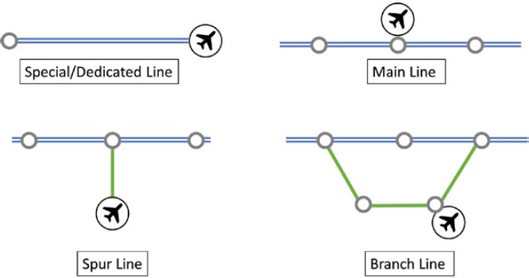
Source: Stubbs and Jegede (1998)
- spur lines would have to travel backward to return to the branch-off station due to the single access point.
- Branch line: The airport terminal is close enough to an existing railway to build an airport station; however, the railway is only a branch line off of the main network.
Intercity and High-Speed Rail
Railway Corridors
Federal Railroad Administration guidance prohibits at-grade crossings for locations where train speeds exceed 125 mph (200 km/h) and for approved barrier systems where train speeds exceed 110 mph. For other train speeds lower than 110 mph, the agency discourages at-grade crossings except for locations where they cannot be eliminated. While there are no mandated safety requirements for operations below 110 mph, along certain corridors where these operations are active, advanced technologies, like four-quadrant gates or incremental train control systems, have been deployed (Morgan et al. 2016). Table 25 depicts the grade crossings for various Federal Railroad Administration–designated track codes and their corresponding operating speeds.
Footprint and Right-of-Way
An intercity or high-speed rail right-of-way should be fully fenced on its perimeter (Acosta 2010). Other right-of-way protection guidelines include the following:
- Fencing should be installed along high-speed rail corridors to restrict unauthorized access to the corridors; this includes fencing along the corridor, at the end of the line, and at passenger stations.
- Vegetation along fenced areas should be controlled to prevent trees and shrubs from providing people and animals with access to the corridor. Fencing and trees should be kept apart by a minimum of 5 feet (2 meters).
- Where high-speed rail corridors are in close proximity to freeway traffic, a rigid traffic barrier made of concrete should be installed. The concrete barrier should have a height between 3 and 5 feet (1 to 2 meters). Fencing may be added above the concrete barrier, if deemed necessary.
- Lateral separation is preferred between conventional rail and high-speed rail. If lateral separation cannot be achieved, a berm, ditch, or physical barrier is adequate if it can effectively stop an out-of-control vehicle from entering adjacent transportation right-of-ways.
Drainage that needs to pass underneath fenced areas should be in an enclosed pipe or culvert to prevent access for unauthorized persons and animals (Acosta 2010).
Table 25. U.S. Federal Regulations for High-Speed Rail Grade Crossings (49 CFR 213.347)
| Track Classification | Maximum Operating Speed | Grade Crossing Requirements |
|---|---|---|
| Track Class 6 and below | 110 mph (177 km/h) | No specific requirements |
| Track Class 7 | 125 mph (201 km/h) | Trains may operate over highway-railroad grade crossings if a Federal Railroad Administration–approved barrier system exists and is functioning |
| Track Class 8 | 160 mph (257 km/h) | All highway-railroad or railroad-railroad grade crossings are prohibited |
| Track Class 9 | 200 mph (322 km/h) |
Electric Propulsion Systems
The system design of electric traction power for rail systems dedicated to high-speed rail operations is specific to those services. For rail systems not operating on electric power but considering switching to electric power, an electrification economic study should be conducted to determine whether electric power is “more advantageous than operation with another form of power, which may or may not be in actual use” (American Railway Engineering and Maintenance-of-Way Association 2021).
High-speed rail system routes should have all tracks electrified for train operation purposes. Where high-speed trains operate on other routes for “access to passenger terminals, maintenance facilities or for through running purposes, only assigned tracks and alternates need be considered for electrification” (American Railway Engineering and Maintenance-of-Way Association 2021). High-speed trains demand significantly more electric power than other passenger trains. As a result, most substations should have two transformers to provide sufficient capacity and redundancy for electric power (American Railway Engineering and Maintenance-of-Way Association 2021).
Station Design
Figure 68 depicts typical facilities for high-speed rail stations. In high-speed rail station design, several factors are considered to determine the type, general size, and space needed. The type of station to construct is determined first. There are two types of train stations by function: terminal and intermediate stations.
- Terminal stations: stations where trains usually start and end trips. These stations are expected to accommodate high numbers of passengers as well as have additional facilities to facilitate turning trains in the opposite direction to begin a trip.
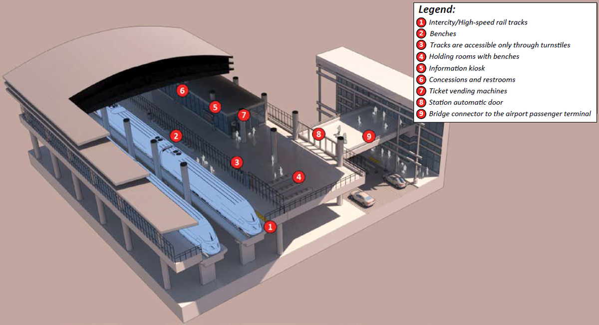
- Intermediate stations: stations with short stay or wait times, unlike terminal stations. Some intermediate stations do not have passenger waiting rooms, in which case passengers usually wait at the platforms for trains.
Major passenger transport stations perform best in already established regional centers. Existing regional centers offer a workable basis for high-speed rail passenger stations due to their employment and residential density, built environment, walkability, and links to local transit networks. Strong megaregional networks are created when hubs are connected to one another. Train travel is most convenient when one or both ends of a route have car-free access.
The location of a station will be chosen by the state department of transportation (DOT) or the High-Speed and Intercity Passenger Rail Authority. The local government will aid in choosing the ideal location to optimize social and economic benefits. Making improvements to existing facilities enables effective use of scarce social resources, such as land and funding for infrastructure. Also, accessibility to destinations may have a significant impact on both early ridership and long-term growth. For example, if there is a short walking route, people will walk from public transportation to employment and other important locations. High-speed rail and intercity station locations can be broken down into four types: urban, suburban, rural, and special use stations (American Railway Engineering and Maintenance-of-Way Association 2021).
- Urban stations: Urban stations, especially those located in or around central business districts, provide several opportunities and significant advantages to travelers accessing these areas. According to the white paper The Power of Urban Rail, urban dwellers are predicted to rise to 75 percent of the global population by 2050; thus, a fast mode of transportation, such as high-speed rail, would effectively transport the public to and from their urban areas (ARUP 2022).
- Suburban stations: Locating a high-speed rail or intercity station in suburban areas would facilitate the ease of passenger movement from cities and central business districts to suburbs. Suburban stations should provide sufficient parking, bike storage, car rental, and other facilities for passengers who prefer to continue their journey by car or bicycle, especially if there are business and leisure destinations around the station’s location.
- Rural stations: Unlike urban and suburban areas, rural areas have low population density and scattered distribution, so finding a geographically feasible location that would be easily accessible to all is difficult. Planning considerations should include accessibility by encouraging new development near the station or locating the station close to the town center, ensuring easy access (American Railway Engineering and Maintenance-of-Way Association 2021).
- Special use stations: Stations at or close to airports differ from the other categories in that they are generally centered around a single significant activity. An airport’s immediate surroundings are often not highly urban in nature; however, through domestic and international flights, airports can attract multimodal connections from locations that are well outside the proposed high-speed rail corridor. Airports’ high-speed train stations are most likely connected to the terminals or have access to them. Parking, vehicle rentals, and other modal amenities could also be shared between an airport station and the airport.
Station facility needs will differ depending on the ridership, nearby land uses, available access options, trip purposes, and other criteria. Station facilities should be able to accommodate different transportation access modes for passengers. Though facility dimensions may vary due to local ordinances and design standards, common data sources, procedures, and rules will be used to guide these decisions (Way 2009). Ridership at the station and the station’s entrance and exit mode splits are two crucial factors to consider when estimating demand and, consequently, the size of a station area space.
The terminal is a key facility, situated between entrances/exits and platforms. Terminal design should be based on facilities and functional needs as well as provide enough space to accommodate the projected passenger volume. Passenger facilities should be designed to deliver LOS B (see Chapter 6) at peak hours on a busy day (Way 2009). Terminals provide passengers with areas for waiting, ticketing, baggage-handling, and concessions.
-
Ticket purchase facility. Facility needs and space requirements will be influenced by the number and various forms of ticketing transactions. Tickets can be purchased via:
- – Ticket stalls/offices, which require office or stall space and queuing space (in addition to selling tickets, a ticket office could offer security and information services);
- – Ticket vending machines, which require space for the machines as well as queuing space; and
- – Pre-purchasing tickets online before arriving at the station.
-
Baggage-handling facilities. A substantial amount of space is required to handle the flow of baggage. The baggage-handling facilities facilitate the flow of baggage between embarking or disembarking passengers and trains through the terminal facilities. According to the distance and number of bags to be accommodated, facilities may be manual, automated, or a combination of methods. A luggage storage facility should also be considered for passengers who need to temporarily leave their baggage or goods at a station. These could include storage lockers or a manned luggage-check room. If available, baggage-handling facilities must be large enough for the following activities:
- – Receipt and checking of outbound baggage,
- – Receipt of inbound baggage from the train and dispensing these items to passengers (baggage claim),
- – Storage of unclaimed and connecting baggage,
- – Storage of baggage tractors and carts, and
- – Storage of cleaning and maintenance supplies.
-
Free area.
- – This is the section of the terminal where people can move freely without tickets. It is located at station entrances, which should be ADA accessible, and includes facilities such as public restrooms, ticketing areas, public circulation, and passenger information desk areas. Seating and provision for visual display as well as audio announcement of train arrival and departure information shall be provided in the free waiting areas. Depending on the type of station, there can be multiple free areas connected by walkways. Table 26 outlines the free area circulation width and waiting area dimensions per the station program design guidelines from the California High-Speed Train Project (Newgard 2011).
-
Paid areas.
- – These areas are located between fare collection lines or security and the platforms. Similar to free areas, paid areas also include circulation spaces, restrooms, and waiting areas, but they are solely used by passengers who possess a valid ticket. Table 27 outlines the paid area circulation width and waiting area dimensions per the station program design guidelines from the California High-Speed Train Project (Newgard 2011).
Table 26. Free Area Circulation Width and Waiting Area Dimensions
| Description | Formula |
|---|---|
| Circulation width | (P15B + P15A) ÷ (15 × 10 people/ft./min.) |
| Waiting area | [(P15B × 1.1) + (P15A × 0.1)] × 14 ft.2 |
Source: Newgard (2011)
Note: P15B = peak 15-minute number of boardings; P15A = peak 15-minute number of arrivals.
Table 27. Paid Area Circulation Width and Waiting Area Dimensions
| Description | Formula |
|---|---|
| Circulation width | (P15B + P15A) ÷ (15 × 10 people/ft./min.) |
| Waiting area | P15B × 14 ft.2 |
Source: Newgard (2011)
Note: P15B = peak 15-minute number of boardings; P15A = peak 5-minute number of arrivals.
-
Amenity space.
- – Passenger amenity spaces are most likely to be located close to areas with major passenger circulation or waiting areas. According to California High-Speed Rail Authority’s Station Program Design Guidelines (Newgard 2011), a standard assumption for passenger amenity space in a station design is shown in Table 28.
Signal and Communication Systems
Signal and control requirements “are established based on the operating environment and speed range of the trains” (American Railway Engineering and Maintenance-of-Way Association 2021). There are various signal and control systems that can be used for different sections of the rail transportation network as long as the systems are compliant with the maximum train speed in their section of the network. The following regulations and guidance relate to this rule:
- Federal Railroad Administration Regulation 49 CFR Part 236.
- Safety of High-Speed Guided Ground Transportation Systems: Collision Avoidance and Accident Survivability, Volume 4: Proposed Specifications, Part 3.6.2, Signal and Train Control Report # DOT-VNTSC-FRA-93.2.IV.
Table 29 provides an overview of the requirements necessary for operation of varying speeds of rail in the United States. The systems introduced in this section primarily involve train control operating systems.
To ensure successful operation of signal systems during train operation, signal bungalows and other signal infrastructure are needed. Signal bungalows and other signal infrastructure are located on the right-of-way, though specific locations are defined by operating requirements and signal design principles (American Railway Engineering and Maintenance-of-Way Association 2021).
There are several types of communication systems for intercity and high-speed rail, and the two share most, if not all, of the same communication considerations. High-speed rail may require enhancements to certain communication systems; however, the specific types of communication system considerations are the same for intercity and high-speed rail.
A complete communications system is not necessary for initial operation of an intercity or high-speed rail system, though the implementation of a complete system should be planned and
Table 28. Passenger Amenity Space Dimensions
| Daily Boarding | Passenger Amenity Space |
|---|---|
| <5,000 | 3,000 sf |
| 5,000 –10,000 | 6,000 sf |
| >10,000 | 10,000 sf |
Source: Newgard (2011)
Note: sf = square feet.
Table 29. Operating Speed Ranges and Movements Permitted
| Operating Speed Range | Movements Permitted |
|---|---|
| Low-Speed Range, 0–59 mph (0–95 km/h) | Manual control with verbal instructions or train orders from an operations control center or dispatcher. Trains operating in territory with no signaling system are restricted to this speed range regardless of onboard train control capabilities. |
| Moderate-Speed Range, 60–79 mph (97–127 km/h) | Manual control using lineside signals. Automatic means of detecting the position of the train on the track structure are used to activate restrictive lineside signals for other trains. At junctions, interlocking systems prevent setting or changing switches or signals to a position that would permit conflicting train movements. |
| High-Speed Range, 80–125 mph (129–201 km/h)a | Permitted movements are the same as the moderate -speed range except that a cab signal system is required and lineside signals are not required. Operation from 80 to 110 mph (129 to 177 km/h) is allowed with automatic cab signals, audible warning whenever the cab signal indication changes to a more restrictive condition, and automatic brake application/propulsion removal if the operator does not adhere to the more restrictive condition within a preset time. An ATP system is highly recommended. |
| Very-High-Speed Range, above 125 mph (201 km/h)a | An ATP system is required. The ATP system must provide positive enforcement of all civil and operational speed limits. If the actual speed exceeds the permitted speed by more than 9 mph (15 km/h), automatic propulsion removal and brake application must be initiated until the actual speed is at or below the permitted speed. Train operator must not be able to override the overspeed correction. |
Source: American Railway Engineering and Maintenance-of-Way Association (2021)
Note: These definitions do not supersede any established speed definitions in applicable operating or maintenance books, federal or state regulations, guidelines, or recommended practices.
a High-speed and very-high-speed train operations must, at a minimum, be protected by a fail-safe control system where the minimum system shall include fail-safe route control and locking, in-cab display of current maximum safe operating speed, current actual speed and overspeed warning, and overspeed protection. If potentially unsafe operation were to occur (i.e., overspeed) and the operator does not take proper action, the system must automatically enforce safe operation.
implanted during construction of the basic system. This allows for easy upgrading of the basic system by adding terminals or modules without the need for a separate communication link (American Railway Engineering and Maintenance-of-Way Association 2021).
Train control systems aim to control the movement of the train throughout the journey in a safe and efficient manner. For trains operating at very high speeds, the minimum requirements for train control systems include informing the operator continuously of the allowable safe speed and automatic application of the train brakes if the operator fails to comply (American Railway Engineering and Maintenance-of-Way Association 2021).
Train control systems are broken into two types of subsystems: vital and non-vital.
- Vital subsystems are the minimum required train control system, in which system components are highly reliable, have a minimum number of known failure modes, and are designed to ensure safe train movement. These subsystems must be fault tolerant and fail-safe. Vital subsystems are responsible for train detection, speed limit determination, route interlocking, and overspeed protection, including actual speed measurement, overspeed determination, and train brake control (American Railway Engineering and Maintenance-of-Way Association 2021).
- Non-vital subsystems are not necessary for safe train control, but they are useful at improving the efficiency of the system’s operation. These subsystems generally improve the train control system and provide information to a central control operator to determine the best way to provide service to passengers. Their implementation must be done in such a way that their function, or lack of function, does not interfere with vital subsystems. Their functions may include “diagnostic functions, route control (automatic or remote), train speed regulation,
- automatic station stopping, scheduling, dispatching, management information (e.g., on time performance, operating statistics, etc.), communications systems, system status display (central control)” (American Railway Engineering and Maintenance-of-Way Association 2021).
Intercity passenger services traveling at speeds below 90 mph (144 km/h) typically do not include a sealed right-of-way; instead, they use deterrent types of rights-of-way fencing for wildlife and trespassers, with passive measures at openings (e.g., public crossings). At speeds up to 110 mph (177 km/h), “additional measures include the use of active warning systems at all grade crossings” (American Railway Engineering and Maintenance-of-Way Association 2021). Corridors with speeds above 110 mph (177 km/h) and up to 125 mph (201 km/h) must have all grade crossings eliminated or secured with impenetrable barriers. Grade crossings are not allowed for high-speed lines that are above 125 mph (201 km/h). A sealed corridor is a comprehensive strategy that includes components like “four-quadrant gates, median treatments, and paired one-way streets with gate arms extending across all lanes of travel, designed to prevent vehicles from driving around lowered gate arms” (Morgan et al. 2016). All corridors use some form of access control at openings (e.g., public crossings). The forms of access control identified include
- Fence: All permanent fencing should be bonded and grounded to prevent electric shock from induced voltage (Acosta 2010). The two types of fencing include access restriction and access deterring fencing. The type of fence used is dependent on the risk of injury, risk of operational disruption, or required level of security.
- Wall: Walls are used to prevent vehicle intrusion into high-speed rail property and mitigate noise and aerodynamic impacts. To protect passengers and patrons at station platforms, walls and fences can be used where there is vertical separation or close proximity between the high-speed rail trackway and adjacent transportation, as well as between main tracks and station tracks (Acosta 2010).
- Traffic Barrier: Traffic barriers vary depending on state standards for rail transportation as well as state regulations and guidance. However, the two general types of traffic barriers are rigid traffic barriers and semiflexible traffic barriers. The type of barrier used depends on what the barrier is guarding against (Acosta 2010).
Additional access control and safety barriers are vegetation control, signage, and gates.
Implementation at Airports
In rail transportation, federal law preempts any state or municipal regulations that are in place to manage or govern rail transportation in order to uphold the Interstate Commerce Clause. The Interstate Commerce Clause gives Congress the power to control commerce between states, with foreign countries, and with federally recognized Tribes. Both federal and state laws must be followed when planning for rail transportation. While federal regulations overrule state regulations where applicable, state rail plans provide a majority of the direction for rail implementation within a state. While implementing new or upgraded passenger-rail service (intercity or otherwise) does not need a state rail plan, PRIIA mandated that states have a plan in order to be approved for federal subsidies for intercity passenger-rail service. Therefore, if a state does not have a state rail plan, it is highly recommended that a state rail plan be drafted and approved to be eligible for funding prior to implementing new rail transportation.
Codes, Regulations, and Design Guidance
The design and operation of both passenger and freight rail lines are aided by federal and state rail laws and codes. However, rather than being tailored to the high-speed rail system, these restrictions are based on conventional rail. As a result, other international rail codes and regulations developed for high-speed rail are used as additional guidance. Table 30 lists existing codes, rules, and standards that can be applied to high-speed rail.
Table 30. High-Speed Rail–Related Codes, Regulations, and Guidelines
| System | Subsystems | Codes and Regulations | Standards and Guidelines |
|---|---|---|---|
| General | NA |
|
|
| Structure | Stations |
|
|
| Bridges and Elevated Structures |
|
|
|
| Tunnels |
|
|
|
| Buildings |
|
|
|
| Utilities | Electrical |
|
|
Source: Way (2009)
Note: AISC = American Institute of Steel Construction; ANSI = American National Standards Institute; AWS = American Welding Society; FEMA = Federal Emergency Management Association; IBC = International Building Code; LRFD = Load and Resistance Factor Design; NA = not applicable; NFPA = National Fire Protection Association; UBC = Uniform Building Code; UIC = International Union of Railways.
Maglev
Infrastructure and Design Elements
Magnetic levitation (maglev) station facilities have design requirements similar to those of high-speed rail and heavy rail—depending on the service being provided—regarding passenger waiting space, corridor sizing, and wayfinding (Figure 69). Unlike conventional train guideways, magnets line the sides of the guideway to center the train cars along the guideway floor to produce levitation through magnetic repulsion, as shown in Figure 70. Maglev cars are equipped with magnets on their sides and undercarriages to complete the magnetic field. This magnetic field can spin motors inside maglev cars, generating the propulsion necessary for them to travel. Since maglev train operations rely on consistently maintaining equal magnetic forces to remain airborne, level, and centered, feedback-control systems need to be put into place to facilitate this.
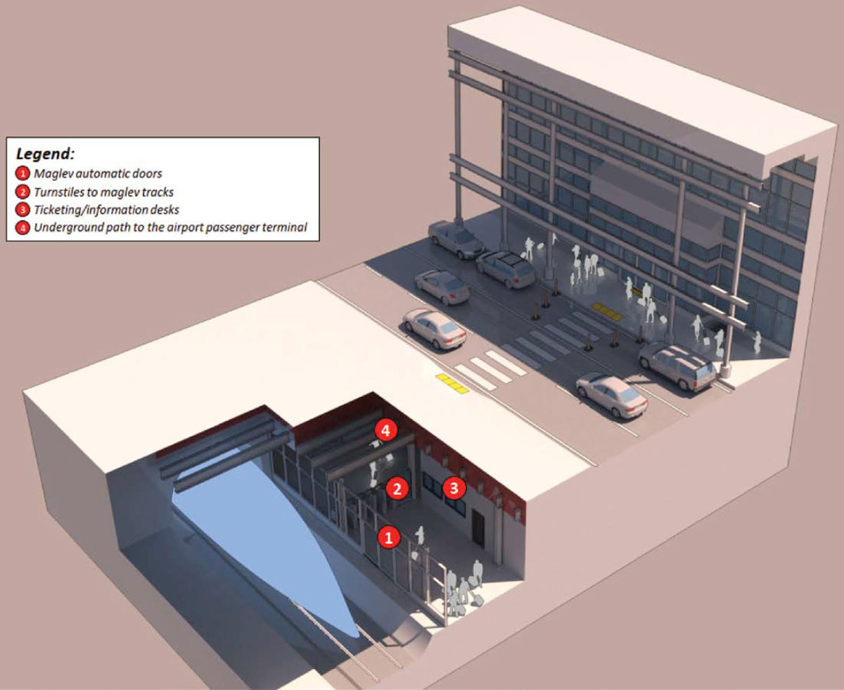
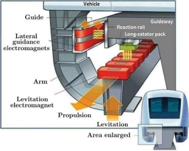
Source: Chavarette (2015)
With no maglev systems in operation or design outside of Asia, few regulatory frameworks have been developed for maglev systems. The German Federal Railway Authority (2007) published a detailed guide of design principles for implementing these systems.
The infrastructure of vactrain technologies, such as hyperloop, is still being researched and developed. However, the primary feature of hyperloop is the tube and pods. Hyperloop is a fixed-guideway transportation mode with the fixed guideway being the tube that the passenger or freight pods travel through. The tubes can be either underground or elevated aboveground on pylons. The tubes are partially evacuated of their air, creating a partial vacuum. “Linear induction motors propel the passenger or freight pods, riding on low-friction air bearings” (Taylor et al. 2016). There are currently no set design requirements or best practices for tube material or diameter. The choice of tube diameter and material affects various components of the hyperloop system, including
- Vehicle size,
- Speed,
- Power consumption,
- Stiffness (i.e., structural strength),
- Leakage,
- Environmental impact, and
- Cost.
While design requirements and best practices have not been set for this emerging technology, the following materials and tube diameters have been identified as preferred by manufacturers (AECOM 2020):
- Material: steel, reinforced concrete, and a combination of steel and reinforced concrete.
- Diameter: 3−5 meters.
There is little information on the materials used in pod design. However, the circumference of the pod would be dependent on the tube it travels through.
Power is anticipated to be supplied by “arrays of solar panels along the guideway,” and claims have been made that these arrays will be able to provide much or all of the required electrical power (Taylor et al. 2016).
Outside of required technology, additional facilities are also needed to operate, manage, and maintain the system, among other tasks. Such facilities include
- Stations (for passenger pick-up and drop-off);
- Dispatch facility;
- Day-to-day system operation, general management, long-term maintenance, personal management, information technology (IT) services, and business development (services could either be incorporated to take place at a station or held at a separate facility); and
- Maintenance, repair, and cleaning facilities.
State of Standards
Hyperloop is still budding as an industry, so there are very few standards associated with it. Organizations like SAE International and Airports Council International (ACI) have yet to publish standards to moderate the new technology. U.S. DOT released the Hyperloop Standards Desk Review (Non-Traditional and Emerging Transportation Technology Council 2021), which does not attempt to form regulations or requirements for the technology but rather provides an overview of potential sources for future regulatory development. However, instead of identifying hyperloop-specific standards, the report identifies an existing regulatory framework that could be applied to hyperloop as its regulatory framework is developed (e.g., U.S. FAA pressurized cabin regulations for pressurized cabins in hyperloop pods).
Aerial Cableway
Overview of Aerial Cableway System
An aerial cableway is a machine that transports people and cargo carriers hanging from cables (Figure 71). It is made up of one or more spans that reach from a loading point to a discharge point, typically over a long distance. The cableway system can either be revolving or reversible.
- Revolving cableway system: The revolving cableway system, also known as the continuous cableway system, uses an operationally detachable clamping mechanism to clamp to the haul rope in a continuous movement. In the stations, the cars (also known as cabins) are slowed down, detached from the haul rope, and directed onto an overhead monorail that travels slowly across the area where passengers board and disembark. Before leaving the station, the car is once more accelerated to the constant haul rope speed and connected to the haul rope by clamping. Figure 72 depicts this system.
- Reversible/jig-back cableway system: The original aerial cableway technology used for transit or general public transportation is the reversible, or jig-back, cableway system. The cable system typically consists of two large cabins that go back and forth between the stations while attached to the same haul cable at opposite ends. When one cabin is at the embarking station, the other is at the disembarking station. Figure 73 depicts this system.
Components
Aerial cableways are made up of five components: cabins, grips, terminals, towers, and cables.
- Cabins (cars): The cabin is the structure used to convey passengers. Depending on the type of aerial cableway technology being employed, passenger cabin sizes may vary. Features that
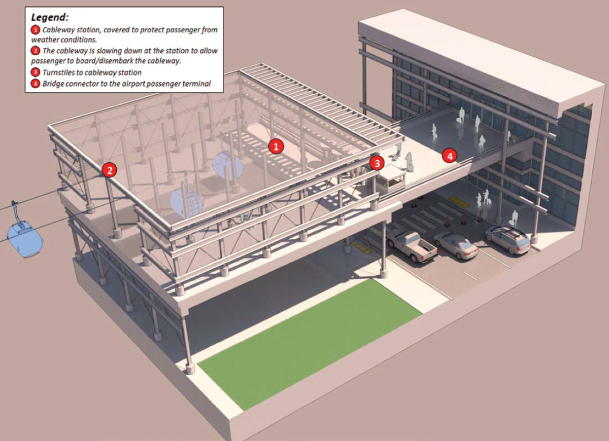
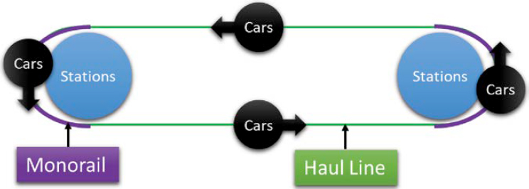
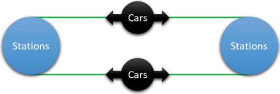
- aim to improve the entire passenger experience can be added to cabins, such as improved ventilation, air conditioning, and Wi-Fi, as well as bicycle racks on their exteriors to appeal to bikers. Additionally, cabins may include onboard one-way or two-way communication systems that might be used to contact passengers in a crisis or for security purposes (Wahl and Schumacher 2018). The cabins must comply with the ADA.
- Grips (carriages): Grips, also known as carriages, connect cabins to the cables. There are two types of grips: detachable and fixed grips. Detachable grips usually go with the revolving cableway system, enabling the cabin to detach from the haul cable and move to the monorail to decelerate and allow for passenger boarding. This type of grip does not disrupt the flow of the entire system. Fixed grips, on the other hand, are attached to the cable permanently; to stop or slow down the cabin, the entire system needs to slow down or come to a stop. Aerial trams and pulse gondolas usually utilize fixed grips (SJC Alliance 2022).
- Terminals (stations): There are three different types of rope terminals: driving terminals, return terminals (at either end of the ropeway), and intermediate terminals (to drop off or pick up people between the drive and return terminals). The terminals include the bull wheels used to move the haul rope. In the driving terminal, the bull wheel can serve as the drive wheel; and in the return terminal, the bull wheel serves as a fixed return mechanism. To provide tensioning for the haul rope, either terminal may contain wheels, counterweights, hydraulic or pneumatic cylinders, or a combination.
-
Towers: Towers hold up the haul and track ropes that connect terminals. They often have steel frames. When securing towers to the ground, consider the soil’s properties and how close it is to bedrock. The purpose of the tower is to support and enable the passage of haul rope through sheaves (wheels) and track rope through saddles for bi- or tri-cable operations (Reconnecting America 2007). In order to prevent carriages from colliding with towers or other objects, towers must also have guides. Aerial cableways are dependent on the minimum vertical clearance, tower spacing, and cable sag (Wahl and Schumacher 2018).
- – Minimum vertical clearance: The variation of tower heights is due to the environment below the system. This ensures that the minimum vertical thresholds are met.
- – Tower spacing: The farther apart the towers are, the higher the towers need to be.
- – Cable sag: Due to downward gravitational pressures acting on the cable and individual cabins, the cable guideway sags between towers; 3.5 percent of the horizontal space between the towers is sagged by the cable guideway. The size of towers must be chosen while accounting for this sag.
- Cables (Ropes): The most crucial component of a cableway is the cables. A strand is created by intertwining many individual wires, while a cable is created by winding several strands together. At one end of the cableway installation, counterweights or anchors are often attached to the cable’s end by sockets. When compared to bi-cableways, monocable systems often have thicker haul ropes that support and move the carriers. A haul cable and a track cable are used in bi-cable systems to propel and support the carriers, respectively. The diameter of both cables is usually smaller than that of monocable systems.
Clearance (Right-of-Way)
In order to avoid line surge under operational conditions and to provide the clearances described in the following list, terminals and towers must be built and constructed. Local wind conditions must be considered.
-
Vertical clearance: The bottom edge of the carrier or ropes must have the following minimum vertical clearances from the ground or other potential obstructions, such as snowpack, along the line between terminal and intermediate station buildings:
- – 5 feet between the lower edge of the carrier and the terrain or other possible obstacles.
- – 8 feet when there is foot passenger traffic under the line.
-
- – 15 feet when there is skiing or controlled vehicle access under the line.
- – 25 feet when there is public vehicle transportation (e.g., roads and railroads) under the line.
-
Horizontal clearance: The minimum distance or clearance between two passing carriers must be the larger of
- – 3.28 feet or
- – 3.28 feet + 0.004(X – 492 feet), where “X” is the cable distance from the point of the carriers passing to the nearest tower or track cable supporting structure.
Design Standards
In the United States, there are no guidelines for the development and execution of aerial cableways. However, like with any means of transportation, there are several critical aspects to properly implementing such a system. The first step is to consult stakeholders who would be affected directly or indirectly by the installation of an aerial cableway. Interact with and involve the affected community, offer public information, and gather any complaints or concerns. Furthermore, because it will be part of public transportation, the suitable lead transit agency—which will carry the project—should be designated.
Station Location
The following factors, as well as any others that may be relevant to the type and location of the aerial tramway, must be considered when choosing the location and alignment of an installation:
- Electric powerlines and supports: Electrical powerlines and support structures should be placed at a distance at least equivalent to the height of the electric poles or supports to prevent poles and electrical lines from touching any area of the cableway, boarding or alighting points or platforms, or tow path, if applicable, in the event of a pole or line collapse.
- Control of space below, above, and adjacent to the installation: No cableway installation shall be permitted to operate when a structure encroaches into the space of the passenger tramway, defined as the area bounded by vertical planes commencing at a point 35 feet from the intersection of the vertical planes of the ropes or cables and ground surface.
- Wind condition: Local wind speed and direction should be considered when locating an aerial tramway. Due to the hanging design of the cabin, heavy winds or crosswinds can impact the movement and stability of the gondola. The bi- and tri-cable gondolas have better wind stability compared to the monocable gondola; planners and designers must select the best location for the desired system and identify which locations will not work.
ADA Accessibility
Previously, boarding persons using wheelchairs required the entire system to come to a halt in order to load and unload wheelchairs—normal boarding usually occurred as the carriers circulated through the station while moving (usually at 50 feet per minute), and there was a vertical gap between the cabin floor and the platform that had to be overcome.
Newer versions have a trench in the platform floor through which the gondola passes, allowing for level loading. Clutching technology also allows an individual carrier to be brought to a near-stop to load wheelchairs without bringing the entire system to a halt.
Urban Air Mobility
Overview
To incorporate urban air mobility (UAM) operations, airports will have to decide whether to accommodate the new traffic on existing facilities (e.g., runways, helipads) or on a new dedicated and separate UAM facility—also known as vertiports—to optimize the overall airport capacity
(Figure 74). Vertiports could be located outside the main air operating area, even on the landside area, where passengers will have to disembark from vertical takeoff and landing (VTOL) aircraft and then reach the terminal to connect to their flight. Vertiports could typically be located on the rooftop of an airport parking garage or any GTC building.
Infrastructure Requirements
A vertiport is a specialized facility designed to accommodate the unique operational requirements of VTOL aircraft. To design such facilities, the FAA (2023b) released Engineering Brief No. 105, Vertiport Design (EB No. 105) as amended, which provides guidance on dimensioning vertiport components based on VTOL characteristics. The document developed standards that are recommended by the FAA to establish an acceptable level of safety, performance, and operation in the design of new civil vertiports and modifications of existing helicopter and airplane landing facilities to accommodate operations of VTOL aircraft. This brief serves as an interim guidance document since it addresses only the landing and takeoff area. For elements such as vertiport taxi routes, VTOL stands, and others, design standards should be retrieved from FAA’s (2023a) AC 150/5390-2D: Heliport Design until the FAA releases an Advisory Circular (AC) on more comprehensive performance-based vertiport design. It is reasonable to derive design standards from AC 150/5390-2D since this approach is confirmed by other technical documents, such as the European Union Aviation Safety Agency’s (2022) Prototype Technical Specifications for the Design of VFR Vertiports for Operation with Manned VTOL-Capable Aircraft Certified in the Enhanced Category (PTS-VPT-DSN).
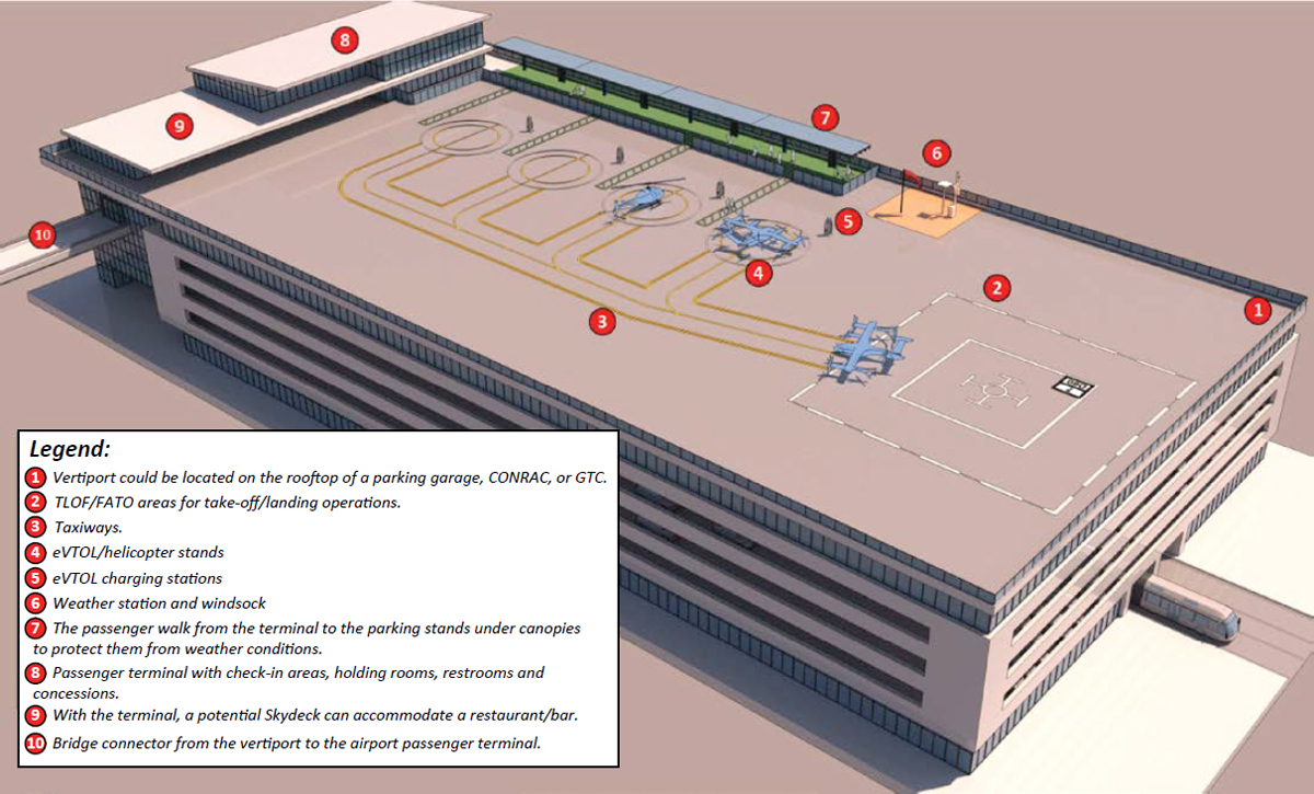
Note: CONRAC = consolidated rental car; eVTOL = electric vertical takeoff and landing; FATO = final approach and takeoff area; GTC = ground transportation center; TLOF = touchdown and liftoff area.
Critical VTOL Aircraft
For planning purposes, the dimensions of vertiport facilities are designed to meet the performance criteria and design characteristics of one or more critical VTOL aircraft. Vertiports, like heliports, are not covered by FAA’s (2017) AC 150/5000-17: Critical Aircraft and Regular Use Determination. However, FAA’s (2023a) AC 150/5390-2D: Heliport Design, Section 108c, defines the design helicopter as “a single or composite helicopter that reflects the maximum weight, maximum contact load/minimum contact area, overall length (D), rotor diameter (RD), tail rotor arc radius, undercarriage dimensions, and pilot’s eye height of all helicopters expected to operate at the heliport.”
To design facilities that share commonalities between helicopters and non-helicopter VTOL aircraft, FAA’s (2023b) EB No. 105 defines a critical VTOL aircraft as “the largest electric, hydrogen, or hybrid VTOL aircraft that is expected to operate at a vertiport. This critical VTOL aircraft is used to size the touchdown and liftoff area (TLOF), FATO [final approach and takeoff area] and Safety Area.” The brief assumes the use of a controlling distance (CD), in lieu of D and RD, as the main design parameter for the vertiport facility dimensional items. CD is defined as “the longest distance between the two outermost opposite points on the aircraft (e.g., wingtip-to-wingtip, rotor tip-to-rotor tip, rotor tip-to-wingtip, or fuselage-to-rotor tip), measured on a level horizontal plane that includes all adjustable components extended to their maximum outboard deflection” (FAA 2023b).
As of this writing, EB No. 105 (FAA 2023b) suggests using a “composite VTOL” for planning and design purposes, with performance criteria and design characteristics derived from nine VTOL models under development (in development or at the prototype stage) and dimensional characteristics in line with the current fleet of VTOL aircraft worldwide.
Vertiport Elements
Based on the critical VTOL aircraft, the following elements can be designed:
- Touchdown and liftoff area: TLOF is a load-bearing area from which VTOL aircraft performs liftoff and touchdown. The TLOF is centered on the FATO (see next bullet). A TLOF can be circular, square, or rectangular in shape.
- Final approach and takeoff area: FATO is a level, load-bearing area surrounding and concentric with the associated TLOF that protects VTOL operations immediately prior to touchdown and just after liftoff.
- Safety area: The safety area provides a buffer should VTOL operations deviate from the FATO; it shall be clear of obstructions. Unlike TLOF and FATO, the safety area does not need to be paved or level nor have load-bearing surfaces; it may also exist over water or otherwise clear airspace.
-
Imaginary surfaces: As defined in 14 CFR 77: Safe, Efficient Use, and Preservation of the Navigable Airspace, imaginary surfaces are applicable to vertiports, which aim to identify any structures that may be penetrating these surfaces. These obstacles require (a) that the FAA be notified and (b) the development of an aeronautical study by the FAA. The “Part 77” imaginary surfaces defined for heliports, shown in Figure 75, remain applicable for vertiports. These surfaces include the following:
- – Primary surface: horizontally and vertically coincident with the FATO.
- – Approach surface: extending laterally and symmetrically from the approach/departure path. Its inner (lower) edge is coincident with the FATO’s edge, from which it extends horizontally for 4,000 feet, reaching a width of 500 feet at its outer edge. Its slope rises vertically at a rate of 8:1.
- – Transitional surface: extending laterally and upward from the primary and approach surfaces, with its lower edges coinciding with the primary and approach surfaces’ lateral edges
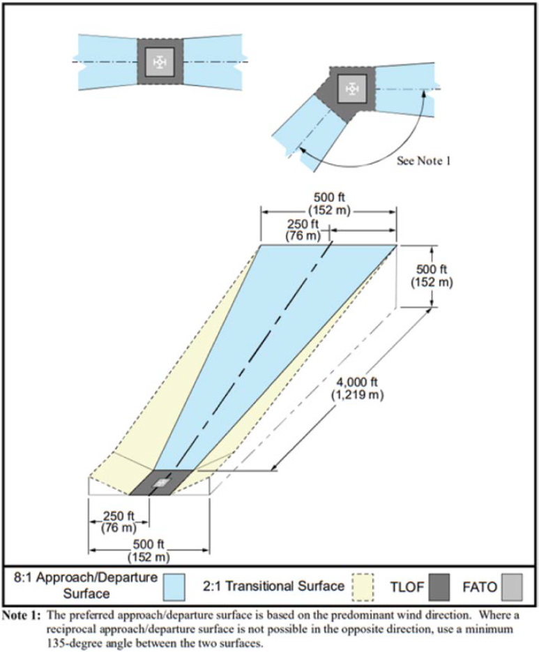
-
- and its outer edges 250 feet away from the primary and approach surfaces’ centerline. Its elevation rises at a 2:1 slope.
- VTOL taxi routes: VTOL taxi routes are obstacle-free corridors on the ground that permit movement of VTOL between different areas of vertiports (such as between stands or between stands and the FATO/TLOF). The taxi route includes the taxiway, plus the appropriate clearances on both sides of the taxiway. There are two types of VTOL taxiways: ground taxiways and hover taxiways. These can be either a paved area (taxiway) plus applicable lateral clearance on both sides or an unpaved area. According to AC 150/5390-2D, ground taxi is the surface movement of a wheeled helicopter under its own power with wheels touching the ground. Hover taxi (also called air taxi) is the movement of a wheeled or skid-equipped helicopter above a surface. For facility design purposes, assume a skid-equipped helicopter is used to hover taxi.
- VTOL stands: Also known as parking positions, stands are generally circular in form and provide a safe location for parking, loading, unloading, and recharging or refueling helicopters
- or VTOL. At a transport heliport, two types of parking positions exist: turnaround and taxi-through. A third position (back-out parking) is only possible at general aviation heliports.
- Pedestrian protection: Passenger walkways should be provided and marked accordingly to safely guide passengers from and to the VTOL aircraft away from the operating area to the terminal or egress/ingress of the VTOL facility. While EB No. 105 (FAA 2023b) provides no guidance on the non-movement area, vertiport markings for pedestrian walkways or pathways can be derived from the recommendations and practices for heliport facilities, such as the FAA’s AC 150/5390-2D; A4A’s Safety Guidelines SG 908: Recommended Apron Markings and Identifications (Section 2.2); ACI’s Apron Markings and Signs Handbook, 3rd Edition, 2017 (Sections 3.15 and 3.16); as well as Markings and Signage of the Traffic Area (Section 2.8) by The French-Speaking Airports (UAF&FA). Additional pedestrian protections can include blast fences and other blast protection devices to protect passengers from the rotor downwash and outwash.
- Rotor downwash and outwash: The operation of VTOL aircraft will cause the air passing near or through the rotors to accelerate and be pushed downward (downwash) or away from the VTOL (outwash); this air moves fast enough to cause injury or property damage. Information on maximum admissible air velocity for asset and pedestrian protection is available in FAA’s AC 150/5300-13B: Airport Design, Appendix C.2.1, with technical information in Sections 5.17.3 and 6.6.2, as well as the Infrastructure Workgroup of The French-Speaking Airports (see Methodology for Assessing Jet Blast Hazard). While these documents are primarily concerned with conventional fixed-wing aircraft, they present technical data and other items that can be useful when defining downwash and outwash exposure areas. Downwash and outwash contours may be available with original equipment manufacturers.
Passenger Terminal
To accommodate AAM passengers, a vertiport terminal may be required, especially for security screening before the VTOL flight. The functionality and shape of these facilities will not differ due to the shape and size of AAM aircraft. Airport practitioners could use guidance from AC 150/5360-13A: Airport Terminal Planning (FAA 2018) and guidelines from ACRP Report 25: Airport Passenger Terminal Planning and Design, Volume 1: Guidebook (Landrum & Brown et al. 2010). Depending on the size and complexity of the vertiport, several facilities need to be available to accommodate passenger needs. These facilities include
- Ticketing. Conventional ticketing counters and kiosks could be utilized for passengers getting boarding passes and those with baggage.
- Concessions/retail. Typical concessions or retail stores could be provided in the terminals for passengers awaiting their flights. These would not only boost passenger experiences but also provide revenue to the facility.
- Hold rooms/security. All passengers are mandated to go through security screening before progressing toward the hold room to await their flight. This ensures that no visitors or unauthorized persons make their way to the hold rooms.
- Baggage services. Although most UAM trips cover short distances, some passengers may carry luggage, especially those traveling to and from airports, thus an area for baggage claim services would come in handy.
- Acceptable spaces for general circulation. Adequate spacing for convenient passenger circulation would bode well for passenger experience and comfort.
- Restrooms.
Terminal planning and design should primarily focus on passenger comfort, experience, and a seamless transition from curbside to aircraft.
Utilities and Support Infrastructure
As mentioned in ACRP Research Report 236 (Le Bris et al. 2022), there are two main alternatives of storing and delivering electrical power to the engine: electrochemical batteries that deliver electricity to the engine and fuel cells that convert hydrogen (and air) into electricity (and water). Three charging or fueling technology solutions are being developed:
- Fixed airport units: electric chargers or hydrant system.
- Mobile airport units: superchargers on trucks or tanker.
- Swap of energy containers: battery or container swap.
Planning and Implementation at an Airport
Two ACRP research reports provide guidelines to help airport practitioners anticipate this new traffic: ACRP Research Report 236 (Le Bris et al. 2022) investigated the impacts of the emergence of electric aviation on the infrastructure, operations, funding, and environment of airports and aviation systems, and ACRP Research Report 243 (Mallela et al. 2023) explored the introduction of AAM at airports and provided a market assessment, as well as emerging use cases with a solid business case for airport applications.
Airports could decide to diversify their ground access by providing AAM connections. As mentioned earlier, AAM operations could operate on existing facilities (runways, helipads), but they would have different needs and require different passenger processes than conventional commercial aviation service; a specific corridor or process would need to be implemented before these passengers are injected into the main terminal. For a certain level of AAM traffic, the airport could decide to develop a dedicated AAM facility, which would probably be located on the landside area. As of this writing, there is too much uncertainty regarding the AAM market evolution to justify investments in such processes; development should be decided on a case-by-case basis, based on the relevance of the AAM business model and forecasts. The dedicated AAM facility will be designed based on a critical AAM vehicle, which also needs to be determined.
Water Transportation
Overview
To increase multimodal transportation, some airports could provide water transportation as a form of ground access, when feasible (Figure 76). This transportation mode can offer either (1) on-demand services to passengers with short or no waiting times through water taxis or shuttles or (2) scheduled public transportation through ferries (or “flying boats” in the future). The main infrastructure components of the three different modes of water transportation (see Chapter 4) are identical and will be presented in this section.
Infrastructure Requirements
According to TCRP Report 152: Guidelines for Ferry Transportation Services (Bruzzone 2012), the main infrastructure components of water transportation include
- Docks: Docks are a general structure or place where a vessel can be moored and where passengers and vehicles embark and disembark.
- Passenger loading areas: Located next to the docks, these areas include walkway facilities to accommodate loading and unloading. They can be on a floating platform or on a platform supported by piling.
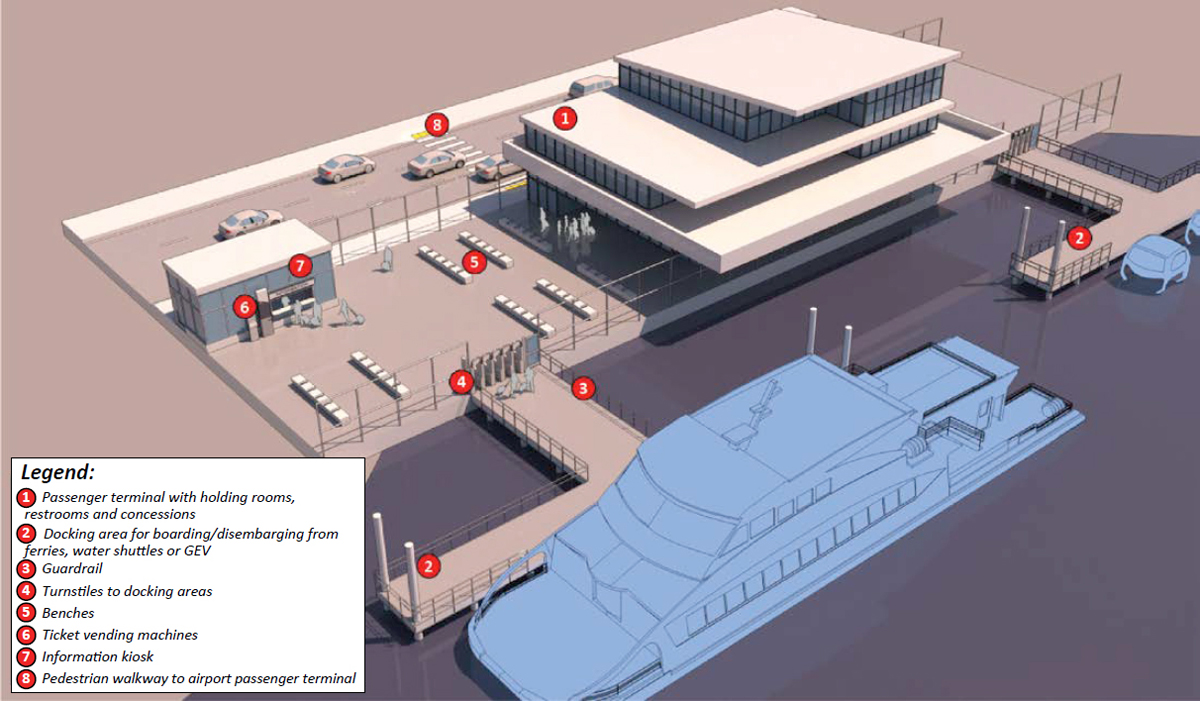
- Ferry terminals: These facilities provide waiting areas for passengers and protection from rain, wind, and sun. Restrooms, vending machines, concessions, and other passenger amenities can be included, depending on the frequency and level of services desired.
Docks
Docking configuration will depend on the critical vessel and the design parameters for capacity and overall travel time. For instance, end-loading ferries have different docking needs than side-loading ferries. In practice, end-loading ferries have achieved wider acceptance as vehicle-carrying ferries, and side-loading has been the most accepted design for passenger-only ferries. The discharge characteristics of all ferries will control the processing compatibility of the docking areas for both passengers and vehicles. The size of the ferry, in terms of its passenger and vehicle capacity, directly controls the scale of the terminal holding facilities.
According to TCRP Report 152 (Bruzzone 2012), there are several safety concerns that should be carefully evaluated:
- Height difference between the dock and the water: To prevent submergence in all but the most extreme conditions, the dock must be high enough above average water level, which can range from several feet to over 20 feet, based on historical data.
- Water-level changes: Waterfront facilities experience different water heights—coastal facilities can face tidal cycles with normal ranges from little more than 1 foot to over 20 feet, whereas non-coastal facilities experience less frequent water-level changes. However, non-coastal water-level changes can sometimes be more severe, with ranges in excess of 20 feet (6 meters). Extreme weather conditions increase the range of changes in water level at all facilities.
- Height difference between the dock and the vessel: There are widely varied and unique height differences for dock-vessel combinations, which also depend on loading and weather conditions.
To mitigate these safety concerns, the following elements should be included:
- Guardrails are critical to ensuring passenger safety because of the inherent dangers of accidentally leaving the path of travel at a marine facility.
- Edge treatments and detectable warnings for the sight-impaired are important for ensuring passenger safety.
- Changes in slopes, heights, materials, and so forth must be carefully considered when planning to account for tides or fluctuations in lake and river levels (e.g., to design a ramp for passengers with disabilities).
- Nonslip surfaces.
- Passenger rescue equipment, which should be easily accessible in case someone falls into the water and requires immediate rescue.
Passenger Loading Area
The passenger loading area is mainly composed of the walkway facilities between the dock and the terminal. Per TCRP Report 152 (Bruzzone 2012), there are two main passenger loading area configurations:
- Side loading, which can be parallel or linear to the dock. There are a variety of berthing arrangements to facilitate a range of vessel types for side loading.
- Bow-loading, which provides the advantage of faster mooring and loading since vessels can maneuver into the dock and “push” against it without tying up. This reduces docking time and provides a wide ramp to allow several streams of passengers into and out of the vessel at one time.
Ferry Terminal
The design of terminals will be influenced by the frequency and level of services desired. Ferry terminals can range from a simple shelter to protect from rain, wind, and sun to a terminal building, featuring waiting areas, ticketing areas, restrooms, vending machines, concessions, and other passenger amenities. As mentioned in TCRP Report 152 (Bruzzone 2012), the appropriate level of seating required has not been determined, but it is correlated to the waiting time. In terminals with an average waiting time below 10 minutes, benches are recommended. When the waiting time increases, more comfortable seating, especially for older people, should be considered.
For passengers arriving at the airport by water transport, the ferry terminal may not necessarily be located next to an airport passenger terminal. If this is the case, a sidewalk should connect the two facilities to allow passengers to walk with their luggage. A canopy may be required to protect passengers from weather conditions. For airports where walking distances may become problematic, a shuttle between the ferry and airport passenger terminals should be provided. For such instances, proper ground access should be planned to allow the shuttle to load and unload passengers and their luggage.
Design Standards
As of this writing, there are no standard designs for water transportation facilities. However, as recommended in TCRP Report 152 (Bruzzone 2012), the facility requirements will largely
depend on the vessels and design parameters for capacity and overall travel time. Similar to aircraft, a critical vessel should be identified in order to design these facilities and size the dimension items.
U.S. Customs and Border Protection (2014) published a report, Guidelines for Ferry Operations in the United States, to provide clarification, uniformity, and standardization throughout the ferry industry. The document recommended that new water transportation facilities should be based on annual forecasts and projected peak traffic from a 5- or 10-year perspective. These facilities shall be the joint responsibility of the U.S. Customs and Border Protection, Immigration and Naturalization Service, Animal and Plant Health Inspection Services, Public Health Service, and U.S. Fish and Wildlife Service.


